
Phau Ntawv Qhia

1. Preliminary Checks
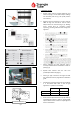
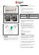
a. Sample probe must be inserted sufficiently, and
ensure sampling is correct when CO
2
/O
2
readings
are measured (refer to Fig.1 for probe position
and insertion).
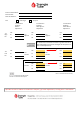
b. Appliance must be operating in service mode at
100% for high fire and 1% for low fire when
CO
2
/O
2
values are measured (Fig.2 / 3). Heating
circuit should have all circulation pumps
operating, providing sufficient flow through the
appliance.
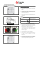
c. Ensure appliance gas valve reference tube is
correctly installed and connected with no kinks or
splits (Fig.4).
d. Replace fiber washers with the new ones
provided (hardware box) (Fig.4).
e. Ensure gas pipe connections are tight and leak
free. See Section 10.5 on page 62 from installation
guide.
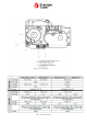
f. Check the incoming gas pressure at the unit (fig.5)
is in accordance with table 2 with all gas
appliances in operation and standby.
Minimum Maximum
Natural Gas
5 in w.c.
13 in w.c.
Propane (LP) 8 in w.c. 12 in w.c.
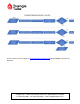
g. If CO
2
is below specified tolerance (as per table 1)
record High fire CO
2
/O
2
in Table 4 – Section 1A &
1B, then follow section 2 and 3 to adjust High and
Low fire Combustion.
Gas pressure sample point
Fig .5
Table 2 – Gas Pressure (inches water column)
Fig .1
Fig .4
Pipe
connections
Fig .2
Fig .3