
Installation manual


RZQG71~140L + RZQSG100~140L7V1+Y1B(9)
Split system air conditioners
4P327537-1 – 2012.08
Installation manual
6
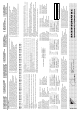
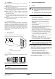
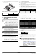
6.2. Installation method for prevention of falling over
If it is necessary to prevent the unit from falling over, install as shown
in the figure.
prep
are all 4 wires as indicated in the drawing
unscre
w the top plate at the 4 locations indicated A and B
put the scr
ews through the nooses and screw them back tight
A Location of the 2 fixation holes on the front side of the unit
B L
ocation of the 2 fixation holes on the rear side of the unit
C Wi
res: field supply
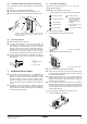
6.3. Drain pipe disposal
Make sure the drain works properly.
In regions
where buildups of snow can be expected, the
accumulation and freezing of snow in the space between the
heat exchanger and external plate may lower operating
efficiency. In this case, drill a knock-out hole in the lower part of
the bottom frame so the snow can escape. When creating a
knock-out hole, use a Ø6 mm drill bit to open round holes
conn
ected to the circumference of the knock-out hole (4 places).
Af
ter punching the knock-out hole, the application of repair-type
paint on the surface around the edge sections is recommended
to prevent rust.
7. Installation service space
The installation service spaces shown in the illustrations are
based on an air intake temperature of 35°C (DB) for COOL
operation. In r
egions where the air intake temperature regularly
exceeds 35°C (DB), or if the heat load of outdoor units is
expe
cted to regularly exceed the maximum operating capacity,
reserve a larger space than that indicated at the air intake side
of units.
Regar
ding the required air outlet space, position the units with
consideration to the space required for the onsite refrigerant
piping work as well. Consult your dealer if the work conditions do
not match those in the drawings.
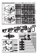
7.1. Precaution on installation
(A) In case of non-stacked installation (See figure 1) (Unit : mm)
(A-1) Single unit inst
allation
(A-2) Multiple units installation (2 units or more)
- Secure appropriate space when using a side piping outlet.
(B) In case of stacked installation
1. In case o
bstacles exist in front of the outlet side.
2. In case o
bstacles exist in front of the air inlet.
Do not e
xceed two levels for stacked installation.
Inst
all a roof cover as shown in the figures above (field supply),
as outdoor units with downward drainage are subject to dripping
and freezing of that drain water.
Inst
all the upper outdoor unit so that its bottom plate is at
sufficient height above the roof cover. This is to prevent the
buildup of ice on the bottom plate outer surface. A space of at
least 500 mm is recommended.
It
is not necessary to install a roof cover if there is no danger of
drainage dripping and freezing. In this case, the space between
the upper and lower outdoor units should be at least 100 mm.
Close t
he gap between the upper and lower units so there is no
re-intake of discharged air.
(C) In case of multiple-row installation (for roof top use, etc.)
1. In case o
f installing one unit per row.
A
C
B
1
2
3
1 Drill
2 Area around knock-
out hole
3 Knock-out hole
Suction side obstacle Obstacle is present
Discharge side obstacle
1 In these cases, close the
bo
ttom of the installation
frame to prevent the
discharged air from being
bypassed
Left side obstacle
Right side obstacle
2 In these cases, only 2 units
can be inst
alled.
Top side obstacle This situation is not allowed
A
A Roof cover (field supply)
A
A Roof cover (field supply)