
Installation manual

Installation manual
19
RZQG71~140L + RZQSG100~140L7V1+Y1B(9)
Split system air conditioners
4P327537-1 – 2012.08
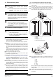
15.4. Precautions regarding test-runs
1 In order to detect stop valves failing to open, operation of the
unit is compulsorily performed in cooling for 2-3 minutes during
the first test run, even if the remote controller was set to heating
operation. In this case, the remote controller will have kept
displaying the heating symbol all the time and the unit will switch
to heating operation automatically after elapse of that time.
2 In case
you cannot operate the unit in test run mode for any
unusual reason, refer to "15.5. Failure diagnosis at the moment
of first installation" on page 19.
3 In case of a
wireless remote controller, execute the test run only
after having installed the indoor unit decoration panel with infra-
red receiver first.
4 In
case the panels of indoor units are not yet installed to the
indoor units, make sure to shut off the power supply after
finishing the complete test run.
5 A complete test ru
n surely includes shutting off power after
having performed a normal operation stop on the remote
controller. Do not stop operation by turning circuit breakers off.
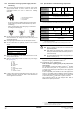
15.5. Failure diagnosis at the moment of first
installation
If the malfunction code "UA" is displayed on the remote
controller, there is a possibility that connection is with
incompatible indoor unit.
In case nothing is displayed on th
e remote controller (the
currently set temperature does not display), check for any of the
following abnormalities before you can diagnose possible
malfunction codes.
D
isconnection or wiring error (between power supply and
outdoor unit, between outdoor unit and indoor units, between
indoor unit and remote controller).
T
he fuse on the outdoor unit PCB may have run out.
If
the malfunction code "E3", "E4", "L8" or "U0" is displayed on the
remote controller, there is a possibility that the stop valves are
closed.
If the
malfunction code "E3", "E4", "L4" or "L8" is displayed on the
remote controller, there is a possibility that air inlet or air outlet
are blocked.
If the
malfunction code "U2" is displayed on the remote
controller, check for voltage imbalance.
If the malfunction code "U4" o
r "UF" is displayed on the remote
controller, check the inter-unit branch wiring connection.
T
he reversed phase protection detector of this product only
works during the initialisation stage after a power reset.
The reversed phase protection detector is
designed to stop the
product in case of an abnormality when the product is started up.
When
the reversed phase protection circuit forced the unit to
stop, check if all phases are existing. If this is the case, shut
off the power supply to the unit and replace two of three
phases. Turn on power again and start the unit.
R
eversed phase detection is not performed while the product
is operating.
In case of
possible reversal of phases after a momentary
black out of power and the power goes on and off while the
product is operating, install a reversed phase protection
circuit on site. Such situation is not unimaginable when using
generators. Running the product in reversed phase can
break the compressor and other parts.
F
or a missing phase in case of Y1 units, "E7" or "U2" will be
displayed on the remote controller of the indoor unit.
Operation will be impossible with either one of these
phe
nomena. If this happens, turn off the power, re-check the
wiring and switch the position of two of the three electrical wires.
(If operation is not possible, do not under any circumstances
force the electromagnetic contactor on.)
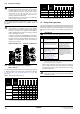
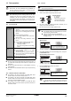
8 Press the Fan
speed/airflow direction button.
Press the Fan speed/airflow
directionbutton.
The main menu screen is displayed
9 Select airflow direction setting by pressing the (right)
button
on the setting screen.
Use the (up) (down) buttons to change the airflow direction.
To select airflow direction setting, press
the (right) button on the setting screen.
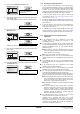
10 After the operation of airflow direction is confirmed, press the
Menu/Enter button.
Change the airflow direction using the
(up) and (down) buttons.
Press the Me
nu/Enter button.
The Basic screen returns.
11 Press and hold the Ca
ncel button for 4 seconds or longer in the
Basic screen.
Press and hold the Cancel button for 4
seconds or longer during backlight lit.
The Service Settings menu is displayed.
12 Select T
est operation in the Service Settings menu and press
the Menu/Enter button.
Press the Menu/Enter button.
The Basic screen returns and normal operation is conducted.
Return Setting
Return Setting
Air Volume/direction
Air Volume Direction
Position 0
Low
Return Setting
Return Setting
Air Volume/direction
Air Volume Direction
Low
Position 0
Cool
Return Setting
Test Operation
Return Setting
Service Settings 1/3
Test Operation
Maintenance Contact
Field Settings
Demand
Min Setpoints Differential
Group Address