
Installation manual

RZQG71~140L + RZQSG100~140L7V1+Y1B(9)
Split system air conditioners
4P327537-1 – 2012.08
Installation manual
18
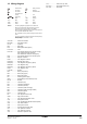
15. Test operation
15.1. Pre-run checks
Be sure to perform a test run.
Be sur
e to fully open the liquid-side and gas-side stop valves. If
you operate the unit with stop valves closed, the compressor will
break down.
Be
sure to execute the first test run of the installation in cooling
mode operation.
Never leave the unit
unattended with an open front panel during
test run.
15.2. Remote controller confirmation
The settings of the remote controller for the BRC1E52 series
should be made in accordance with procedure 15.3.
The
settings of the remote controller for the BRC1E51 series
should be made in accordance with the procedure mentioned in
the remote controller installation manual.
The settings o
f the remote controller for the BRC1D series
should be made in accordance with the procedure mentioned in
the service manual.
15.3. Test run
1 Be sure to turn power on at least 6 hours before starting
operation in order to protect the compressor.
2 Make sur
e the liquid and gas stop valves are open.
3 Be su
re to close the frontside panel before operation, as not
doing so can cause electric shock.
4 Be su
re to set the unit to cooling operation mode.
DANGER
Never leave the unit unattended during installation or
servicing. Whe
n the service panel is removed live parts
can be easily touched by accident.
INFORMATION
Note that during the first running period of the unit,
required power input may be higher than stated on the
nameplate of the unit. This phenomenon originates from
the compressor that needs elapse of a 50 hours run in
period before reaching smooth operation and stable power
consumption.
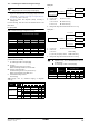
Items to check
Electrical wiring
Inter-unit wiring
Ground wire
Is the wiring as mentioned on the wiring
diagram?
Make sure no wiring has been forgotten and
that there
are no missing phases or reverse
phases.
Is t
he unit properly grounded?
Is the wir
ing between units connected in
series correct?
Are any of the
wiring attachment screws
loose?
Is t
he insulation resistance at least 1 M?
- Use a 500 V mega-tester when
measuring in
sulation.
- Do not use a mega-tester for low-voltage
circuits.
Refrigerant
piping
Is the size of the piping appropriate?
Is the
insulation material for the piping
attached securely?
Are both the liquid and gas pipes insulated?
Are the stop valves for both the liquid side
and the gas side open?
Extra refrigerant
Did you write down the extra refrigerant and
the refrigerant piping length?
NOTICE
Do not interrupt the test run.
NOTICE
The
backlight will be lit for approximately 30 seconds
by pressing any operation button.
Operate th
e buttons when the backlight is lit.
However, On/Off can be operated directly when the
backlight is not lit.
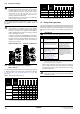
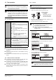
5 Press and hold the Cancel button for
4 seconds or longer.
<Basic screen>
Press and hold the Cancel button for
4 seconds or longer during backlight lit.
The Service Setting menu is displayed
6 Select T
est operation in the Service Settings menu, and press
the Menu/Enter button.
<Service Settings menu screen>
Press the Menu/Enter button.
The Basic screen returns and Test operation is displayed.
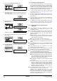
7 Press the ON/OF
F button within ±10 seconds.
The test operation starts.
Press the ON/OFF button within
±10 seconds.
Check operation condition for 3 minutes.
INFORMATION
In case the above mentioned procedures 5 and 6 are
performed in reverse order, test operation can start as
well.
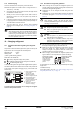
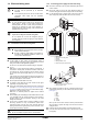
A
B
Opening direction
A Liquid side
B Gas side
Remove the cap and turn
counterclockwise with a
hex wrench until it stops
Cool
Set to
Cool
28
°C
Return Setting
Service Settings 1/3
Test Operation
Maintenance Contact
Field Settings
Demand
Min Setpoints Differential
Group Address
Cool
Return Setting
Test Operation