
Installation manual

RZQG71~140L + RZQSG100~140L7V1+Y1B(9)
Split system air conditioners
4P327537-1 – 2012.08
Installation manual
12
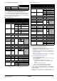
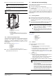
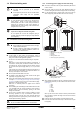
Be sure to insulate the liquid and gas-side field piping.
(The highest temperature that the gas-side piping can reach is
around 120°C, so be sure to use insulating material which is
very resistant.)
1 Compressor
2 I
ndoor and outdoor field piping
3 S
ealant, etc.
4 I
nsulation material
A Wi
nd heat insulation material around the piping section so
it is not exposed and then cover the insulation material with
vinyl tape.
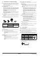
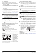
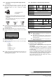
10.3. Cautions for necessity of a trap
To avoid the risk of oil held inside the riser piping flowing back into the
compressor when stopped and causing liquid compression
phenomenon, or cases of deterioration of oil return, it will be
necessary to provide a trap at each difference in height of 10 m in the
riser gas piping.
T
rap installation spacing. (See figure 6)
A Outdoor unit
B I
ndoor unit
C G
as piping
D L
iquid piping
E Oil tr
ap
H I
nstall trap at each difference in height of 10 m.
A trap is not necessary when the outdoor unit is installed at
higher position than the indoor unit.
11. Leak test and vacuum drying
When all piping work is complete and the outdoor unit is connected to
the indoor unit, it is necessary to:
ch
eck for any leakages in the refrigerant piping
to perform vacu
um drying to remove all moisture in the
refrigerant piping.
If there is a possibility of moistur
e being present in the refrigerant
piping (for example, rainwater may have entered the piping), first
carry out the vacuum drying procedure below until all moisture has
been removed.
11.1. General guidelines
All piping inside the unit has been factory tested for leaks.
Use
a 2-stage vacuum pump with a non-return valve which can
evacuate to a gauge pressure of –100.7 kPa (5 Torr absolute,
–755 mm Hg).
Connect the vacuum pump to bo
th the service port of the gas
stop valve and the liquid stop valve to increase efficiency.
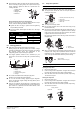
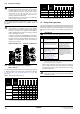
11.2. Setup
(See figure 8)
1 Pressure gauge
2 Nitrog
en
3 Refrig
erant
4 W
eighing machine
5 V
acuum pump
6 S
top valve
11.3. Leak test
The leak test must satisfy specification EN378-2.
1 V
acuum leak test
1.1 Evacuate the system fr
om the liquid and gas piping to
–100.7 kPa (5 Torr).
1.2 Once rea
ched, turn off the vacuum pump and check that
the pressure does not rise for at least 1 minute.
1.3 Should the
pressure rise, the system may either contain
moisture (refer to the paragraph "Vacuum drying") or have
leaks.
2 Pressu
re leak test
2.1 Br
eak the vacuum by pressurizing with nitrogen gas to a
minimum gauge pressure of 0.2 MPa (2 bar).
Never set the gauge pressure higher than the maximum
ope
ration pressure of the unit, i.e. 4.0 MPa (40 bar).
2.2 T
est for leaks by applying a bubble test solution to all piping
connections.
2.3 Discha
rge all nitrogen gas.
NOTICE
Any exposed piping may cause condensation.
DANGER
Do not touch piping and internal parts.
1
3
4
A
2
NOTICE
Do not purg
e the air with refrigerants. Use a vacuum
pump to evacuate the installation. No additional
refrigerant is provided for air purging.
Make sur
e that the gas stop valve and liquid stop
valve are firmly closed before performing the leak test
or vacuum drying.
NOTICE
Make sure to use a recommended bubble test solution
from your wholesaler.
Do not use soap water, which may cause cracking of
flare nut
s (soap water may contain salt, which absorbs
moisture that will freeze when the piping gets cold),
and/or lead to corrosion of flared joints (soap water
may contain ammonia which causes a corrosive effect
between the brass flare nut and the copper flare).