
Installation manual

RZQG71~140L + RZQSG100~140L7V1+Y1B(9)
Split system air conditioners
4P327537-1 – 2012.08
Installation manual
10
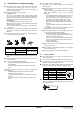
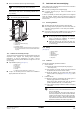
When loosening a flare nut, always use two wrenches together.
When connecting the piping, always use a spanner and torque
wrench toge
ther to tighten the flare nut to prevent flare nut
cracking and leaks.
1 T
orque wrench
2 S
panner
3 P
iping union
4 Flare nut
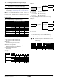
Not recommended, but in case of emergency
Should you be forced to connect the piping without a torque
wrench, follow the followin
g installation method:
T
ighten the flare nut using a spanner until the tightening
torque suddenly increases.
Fro
m that position further tighten the flare nut to the angle
listed below:
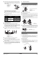
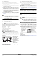
9.2. Brazing guidelines
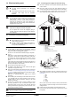
Make sure to blow through with nitrogen when brazing.
Blowing through with nitrogen prevents the creation of large
quantities of
oxidized film on the inside of the piping. An oxidized
film adversely affects valves and compressors in the
refrigerating system and prevents proper operation.
The nitrog
en pressure should be set to 0.02 MPa (i.e., just
enough so it can be felt on the skin) with a pressure-reducing
valve.
1 Refrigerant piping
2 P
art to be brazed
3 Ta
pi ng
4 Ma
nual valve
5 P
ressure-reducing valve
6 Nitro
gen
Do not use anti-oxidants when brazing the pipe joints.
Residue can clog pipes and break equipment.
Do not
use flux when brazing copper-to-copper refrigerant
piping. Use phosphor copper brazing filler alloy (BCuP) which
does not require flux.
Flux
has an extremely harmful influence on refrigerant piping
systems. For instance, if chlorine based flux is used, it will cause
pipe corrosion or, in particular, if the flux contains fluorine, it will
deteriorate the refrigerant oil.
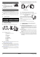
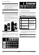
9.3. Stop valve operation
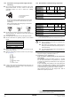
Cautions on handling the stop valve
Make sure to keep both stop valves open during operation.
The
figure below shows the name of each part required in
handling the stop valve.
The stop valve is fact
ory closed.
Do not a
pply excessive force to the valve stem. Doing so may
break the valve body.
Since the sto
p valve attachment plate may be deformed if only a
torque wrench is used to loosen or tighten the flare nut, always
make sure to secure the stop valve with a spanner, then loosen
or tighten the flare nut with a torque wrench.
Do not place the spanner on the stem cap, a
s this could cause a
refrigerant leak.
When it is exp
ected that the operating pressure will be low (for
example, when cooling will be performed while the outside air
temperature is low), sufficiently seal the flare nut in the stop
valve on the gas line with silicon sealant to prevent freezing.
Opening/closing the stop valve
Opening the stop valve
1. Remove the valv
e cover.
2. Insert a
hexagon wrench (liquid side: 4 mm/gas side: 6 mm) into
the valve stem and turn the valve stem counterclockwise.
3. When the va
lve stem cannot be turned any further, stop turning.
The valve is now open.
Closing the stop valve
1. Remove the valv
e cover.
2. Insert a
hexagon wrench (liquid side: 4 mm/gas side: 6 mm) into
the valve stem and turn the valve stem clockwise.
3. When the va
lve stem cannot be turned any further, stop turning.
The valve is now closed.
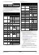
Piping size
(mm)
Further tightening angle
(degrees)
Recommended arm length
of spanner (mm)
Ø6.4
60~90
150
Ø9.5 200
Ø12.7
30~60
250
Ø15.9 300
Ø19.1 20~35 450
1
2
43
15432
66
Silicon sealant
(Make sure there is no gap)
Closing direction
Liquid side Gas side
1
2
3
4
1 Service port and service port cap
2 Valve stem
3 Field piping connection
4 Stem cap
1
2
1 Spanner
2 Torque wrench