INSTALLATION MANUAL Split system air conditioners RZQG71L7V1B RZQG100L7V1B RZQG125L7V1B RZQG140L7V1B RZQG71L7Y1B9 RZQG100L7Y1B RZQG125L7Y1B RZQG140L7Y1B RZQSG100L7V1B RZQSG125L7V1B RZQSG140L7V1B RZQSG100L7Y1B9 RZQSG125L7Y1B9 RZQSG140L7Y1B
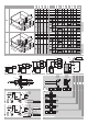
1 (A-1) 1 (A-2) 1 > 1100 00 > 1100 00 2 1 6 E L3 4 L2 H1 2 L1 H2 H2 L3 H1 L1 H1 L1 L3 L4 L1 C L6 5 7 9 A B 3 L3 D 4 3 L5 H1 L2 2 A L4 H2 L2 3 6 V1 type 1~50 Hz 220-240 V Y1 type 3N~50 Hz 380-415 V L1 L2 L3 1 2 1 2 4 5 L1 L2 L3 N 7 8 6 1 3 3 R410A 2 4 5 6 1 3 8 R410A 7 2 8 4 5 B 9 9 H 5
CE - DECLARACION-DE-CONFORMIDAD CE - DICHIARAZIONE-DI-CONFORMITA CE - ∆HΛΩΣΗ ΣΥΜΜΟΡΦΩΣΗΣ CE - ERKLÆRING OM-SAMSVAR CE - ILMOITUS-YHDENMUKAISUUDESTA CE - PROHLÁŠENÍ-O-SHODĚ 01 ** 02 ** 03 ** 04 ** 05 ** 06 ** as set out in and judged positively by according to the Certificate . wie in aufgeführt und von positiv beurteilt gemäß Zertifikat . tel que défini dans et évalué positivement par conformément au Certificat .
RZQG71~140L7V1B RZQG71L7Y1B9 RZQG100~140L7Y1B RZQSG100~140L7V1B RZQSG100+125L7Y1B9 RZQSG140L7Y1B Content Page CAREFULLY READ THESE INSTRUCTIONS BEFORE INSTALLATION. THEY WILL TELL YOU HOW TO INSTALL AND HOW TO CONFIGURE THE UNIT PROPERLY. KEEP THIS MANUAL IN A HANDY PLACE FOR FUTURE REFERENCE. 1. Definitions.................................................................................. 1 1.1. 1.2. Installation manual Split system air conditioners Meaning of warnings and symbols...................
Service company: Qualified company which can perform or coordinate the required service to the unit. Warning Ask your dealer or qualified personnel to carry out installation work. Do not install the machine by yourself. Improper installation may result in water leakage, electric shocks or fire. Perform installation work in accordance with this installation manual. Improper installation may lead to water leakage, electric shocks or fire.
Caution Earth the unit. Earthing resistance should be according to applicable legislation. Do not connect the earth wire to gas or water pipes, lightning conductor or telephone earth wire. Incomplete earthing may cause electric shocks. Gas pipe. Ignition or explosion may occur if the gas leaks. Water pipe. Hard vinyl tubes are not effective earths.
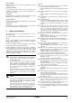
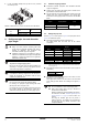
3.4. 5. Installation For installation of the indoor unit(s), refer to the indoor unit installation manual. Illustrations show RZQG125L outdoor unit type. Other types also follow this installation manual. This outdoor unit requires the pipe branching kit (optional) when used as the outdoor unit for the simultaneous operation system. Refer to catalogues for details.
Install a baffle plate on the air suction side of the outdoor unit and set the outlet side at a right angle to the direction of the wind: In heavy snowfall areas it is very important to select an installation site where the snow will not affect the unit and set the outlet side at a right angle to the direction of the wind: 1 2 3 3 Prepare a water drainage channel around the foundation, to drain waste water from around the unit.
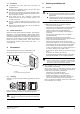
6.2. Installation method for prevention of falling over If it is necessary to prevent the unit from falling over, install as shown in the figure. prepare all 4 wires as indicated in the drawing unscrew the top plate at the 4 locations indicated A and B put the screws through the nooses and screw them back tight 7.1.
2. In case of installing multiple units (2 units or more) in lateral connection per row. 8.1. Construction material: phosphoric acid deoxidised seamless copper for refrigerant. Temper grade: use piping with temper grade in function of the pipe diameter as listed in table below. The pipe thickness of the refrigerant piping should comply with relevant local and national regulations. The minimal pipe thickness for R410A piping must be in accordance with the table below.
8.3. Selection of branch pipe For RZQSG units only Allowable pipe length Allowable pipe length RZQ(S)G71~140L7Y1B(9)+ FCQG35~71F/FCQHG71F Twin KHRQ22M20TA KHRQ58T Triple KHRQ127H KHRQ58H Double twin KHRQ22M20TA (3x) KHRQ58T (3x) 8.4.
9. Precautions on refrigerant piping Do not allow anything other than the designated refrigerant to get mixed into the freezing cycle, such as air, etc. If any refrigerant gas leaks while working on the unit, ventilate the room thoroughly right away. Use R410A only when adding refrigerant Installation tools: Make sure to use installation tools (gauge manifold, charge hose, etc.) that are exclusively used for R410A installations to withstand the pressure and to prevent foreign materials (e.g.
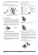
When loosening a flare nut, always use two wrenches together. When connecting the piping, always use a spanner and torque wrench together to tighten the flare nut to prevent flare nut cracking and leaks. 1 Torque wrench 1 2 Spanner 3 Piping union 4 Flare nut 2 4 Tighten the flare nut using a spanner until the tightening torque suddenly increases. From that position further tighten the flare nut to the angle listed below: Further tightening angle (degrees) Ø6.4 Ø12.7 Ø19.1 9.2.
Cautions on handling the stem cap The stem cap is sealed where indicated by the arrow. Take care not to damage it. After handling the stop valve, make sure to tighten the stem cap securely. For the tightening torque, refer to the table below. Check for refrigerant leaks after tightening the stem cap. 1 Always use a charge hose equipped with a valve depressor pin, since the service port is a Schrader type valve.
Be sure to insulate the liquid and gas-side field piping. NOTICE Any exposed piping may cause condensation. (The highest temperature that the gas-side piping can reach is around 120°C, so be sure to use insulating material which is very resistant.) DANGER Do not touch piping and internal parts. 11.
11.4. Vacuum drying 12.2. Precautions and general guidelines To remove all moisture from the system, proceed as follows: When servicing the unit requires the refrigerant system to be opened, treatment and evacuation of refrigerant must be done in accordance with applicable legislation. Refrigerant can not be charged until field wiring has been completed. Refrigerant may only be charged after performing the leak test and vacuum drying (see "11. Leak test and vacuum drying" on page 12).
12.3. Calculating the additional refrigerant charge Example 1 NOTICE L2=7 (Ø6.4) 50 type Piping length is the one way length of liquid piping. The additional charging amounts relate to the refrigerant piping length as in "Maximum total one-way piping length" of the table in paragraph "8.4. Allowable pipe length and height difference" on page 8. (E.g. twin: L1+L2+L3). Over 30 m, please add refrigerant quantity according to following table. indoor L3=5 (Ø6.4) 50 type outdoor heat pump 1.
12.4. Complete recharging 10~15 m 15~20 m 20~25 m Before recharging, make sure to execute vacuum drying of the internal piping of the unit as well. To do so, use the internal service port of the unit. Do NOT use the service ports located on the stop valve (see "9.3. Stop valve operation" on page 10), since vacuum drying can not be performed properly from these ports. Outdoor units have 1 port on the piping. It is between the heat exchanger and the 4-way valve. size-up 1.9 2.4 2.9 3.4 3.
14. Electrical wiring work 14.2. Connecting power supply and inter-unit wiring Secure the earth wire to the stop valve attachment plate so that it does not slide. WARNING All wiring must be performed by an authorized electrician. Secure the earth wire to the stop valve attachment plate one more time along with the electric wiring and the inter-unit wiring. All components procured on the site and all electric construction shall comply with the applicable legislation.
14.3. Precautions on wiring of power supply and interunit wiring Use a round crimp-style terminal for connection to the power supply terminal board. In case it cannot be used due to unavoidable reasons, be sure to observe the following instruction. 14.4. Specifications of standard wiring components 71V1 100V1 125V1 140V1 71Y1 100Y1 125Y1 140Y1 Minimum circuit amps (MCA)(a) RZQG 20.6 32.0 14.0 21.
15. Test operation 15.3. Test run NOTICE DANGER Never leave the unit unattended during installation or servicing. When the service panel is removed live parts can be easily touched by accident. INFORMATION Do not interrupt the test run. 1 Be sure to turn power on at least 6 hours before starting operation in order to protect the compressor. 2 Make sure the liquid and gas stop valves are open.
8 Press the Fan speed/airflow direction button. 1 In order to detect stop valves failing to open, operation of the unit is compulsorily performed in cooling for 2-3 minutes during the first test run, even if the remote controller was set to heating operation. In this case, the remote controller will have kept displaying the heating symbol all the time and the unit will switch to heating operation automatically after elapse of that time.
16. Wiring diagram Y1S........................ Solenoid 4-way valve Z1C~Z7C ...............
4P327537-1 2012.