
Specifications

SiUS12-928_A Main Functions
Function and Control 32
1.4 Fan Speed Control for Indoor Units
Outline Phase control and fan speed control contains 9 steps: LLL, LL, SL, L, ML, M, MH, H, and HH.
The airflow rate can be automatically controlled depending on the difference between the room
thermistor temperature and the target temperature. This is done through phase control and Hall IC
control.
For more information about Hall IC, refer to the troubleshooting for fan motor on page 106, 107.
Automatic Fan
Speed Control
In automatic fan speed operation, the step “SL” is not available.
= The airflow rate is automatically controlled within this range when the FAN setting button
is set to automatic
.
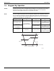
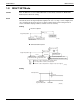
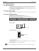
<Cooling>
The following drawing explains the principle of fan speed control for cooling.
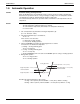
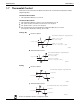
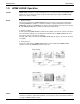
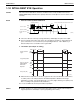
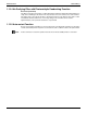
<Heating>
In heating mode, the fan speed is regulated according to the indoor heat exchanger temperature
and the difference between the room thermistor temperature and the target temperature.
Note: 1. During POWERFUL operation, fan rotates at H tap + 50 ~ 90 rpm.
2. Fan stops during defrost operation.
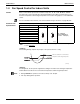
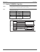
Step Cooling Heating Dry
LLL
750 - 1000 rpm
(During POWERFUL
operation : 1050 rpm)
LL
SL
L
ML
M
MH
H
HH (POWERFUL)
(R6833)
(R6833)
+1.5˚C (2.7˚F)
+0.5˚C (0.9˚F)
+2˚C (3.6˚F)
+1˚C (1.8˚F)
M
ML
L
Fan speed
Difference between the room thermistor
temperature and the target temperature
(R12403)