
Specifications


SiUS12-928_A Check
Service Diagnosis 158
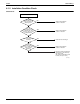
6.1.14 Hall IC Check
Check No.16 1. Check the connector connection.
2. With the power on, operation off, and the connector connected, check the following.
∗Output voltage of about 5 V between pins 1 and 3.
∗Generation of 3 pulses between pins 2 and 3 when the fan motor is operating.
If NG in step 1 Defective PCB Replace the PCB.
If NG in step 2 Defective Hall IC Replace the fan motor.
If OK in both steps 1 and 2 Replace the PCB.
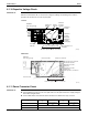
6.1.15 Main Circuit Short Check
Check No.29 Measure the resistance between pins at both ends of DB1.
If the resistance is ∞ or less than 1 kΩ, the main circuit short.
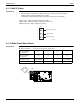
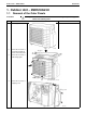
1
Gray (power supply)
Purple (signals)
Blue (grounding)
2
3
(R12398)
S7
(–) terminal of the tester
(in case of digital,
(+) terminal)
(~) (+) (~) (–)
(+) terminal of the tester
(in case of digital,
(–) terminal)
(+) (~) (–) (~)
Resistance in OK
several kΩ
~several MΩ
∞∞
several kΩ
~several MΩ
Resistance in NG 0 or
∞ 000 or ∞
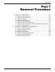
TB2
>PS<
TB3
P2 N1
S90 S92 S93
S80
S20 S21 S22
S40
(R11690)
DB1
+
–
~
~