
Service manual

SiUS28-902_a
65 Troubleshooting
Part 7
Troubleshooting
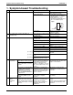
1. Symptom-based Troubleshooting .........................................................67
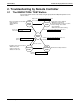
2. Troubleshooting by Remote Controller .................................................70
2.1 The INSPECTION / TEST Button .......................................................... 70
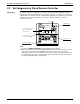
2.2 Self-diagnosis by Wired Remote Controller ........................................... 71
2.3 Self-diagnosis by Wireless Remote Controller....................................... 72
2.4 Operation of the Remote Controller’s Inspection /
Test Operation Button............................................................................ 75
2.5 Remote Controller Service Mode ........................................................... 76
2.6 Remote Controller Self-Diagnosis Function...........................................78
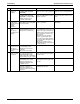
3. Troubleshooting by Indication on the Remote Controller......................85
3.1 “A0” Indoor Unit: Error of External Protection Device ............................. 85
3.2 “A1” Indoor Unit: P.C.B. Defect............................................................... 86
3.3 “A3” Indoor Unit: Malfunction of Drain Level Control System (S1L)........87
3.4 “A6” Indoor Unit: Fan Motor (M1F) Lock, Overload ................................ 89
3.5 “A7” Indoor Unit: Malfunction of Louver Motor (M1S) .............................90
3.6 “A9” Indoor Unit: Malfunction of Moving Part of
Electronic Expansion Valve (Y1E) ......................................................... 92
3.7 “AF” Indoor Unit: Drain Level above Limit ............................................... 94
3.8 “AJ” Indoor Unit: Malfunction of Capacity Determination Device............95
3.9 “C4” Indoor Unit: Malfunction of Thermistor (R2T) for
Heat Exchanger .....................................................................................96
3.10 “C5” Indoor Unit: Malfunction of Thermistor (R3T) for Gas Pipes ...........97
3.11 “C9” Indoor Unit: Malfunction of Thermistor (R1T) for Suction Air ..........98
3.12 “CA” Indoor Unit: Malfunction of Thermistor for Discharge Air ................ 99
3.13 “CJ” Indoor Unit: Malfunction of
Thermostat Sensor in Remote Controller ............................................100
3.14 “E1” Outdoor Unit: P.C.B. Defect .......................................................... 101
3.15 “E3” Outdoor Unit: Actuation of High Pressure Switch .........................102
3.16 “E4” Outdoor Unit: Actuation of Low Pressure Sensor .........................104
3.17 “E5” Inverter Compressor Motor Lock................................................... 106
3.18 “E7” Malfunction of Outdoor Unit Fan Motor .........................................108
3.19 “E9” Outdoor Unit: Malfunction of Moving Part of
Electronic Expansion Valve (Y1E) .......................................................109
3.20 “F3” Outdoor Unit: Abnormal Discharge Pipe Temperature .................111
3.21 “F6” Outdoor Unit: Refrigerant Overcharged ........................................112
3.22 “H9” Outdoor Unit: Malfunction of Thermistor (R1T) for Outdoor Air ....113
3.23 “J3” Outdoor Unit: Malfunction of Discharge Pipe Thermistor (R2T)....114
3.24 “J5” Outdoor Unit: Malfunction of Thermistor (R3T, R5T) for
Suction Pipe 1, 2 .................................................................................. 115
3.25 “J6” Outdoor Unit: Malfunction of Thermistor (R4T) for
Outdoor Unit Heat Exchanger..............................................................116
3.26 “JA” Outdoor Unit: Malfunction of High Pressure Sensor .....................117