SiUS28 - 902_a SiUS28-902 06/2009 AK Service Manual / SkyAir Inverter R-410A Heat Pump 60Hz / P Series SiUS28-902 Specifications, designs and other content appearing in this brochure are current as of June 2009 but subject to change without notice.
SiUS28-902_a SkyAir Inverter P Series R-410A Heat Pump 60Hz 1. Introduction ............................................................................................. v 1.1 Safety Considerations for Repair ............................................................. v 1.2 Safety Considerations for Users ............................................................. vi Part 1 General Information........................................................... 1 1. Model Names and Power Supply.................
SiUS28-902_a 3.6 Stopping Operation ................................................................................ 27 3.7 Pressure Equalization Prior to Startup ................................................... 28 4. Protection Control .................................................................................29 4.1 4.2 4.3 4.4 High Pressure Protection Control .......................................................... 29 Low Pressure Protection Control ..........................................
SiUS28-902_a 3.9 “C4” Indoor Unit: Malfunction of Thermistor (R2T) for Heat Exchanger ..................................................................................... 96 3.10 “C5” Indoor Unit: Malfunction of Thermistor (R3T) for Gas Pipes ........... 97 3.11 “C9” Indoor Unit: Malfunction of Thermistor (R1T) for Suction Air .......... 98 3.12 “CA” Indoor Unit: Malfunction of Thermistor for Discharge Air ................ 99 3.13 “CJ” Indoor Unit: Malfunction of Thermostat Sensor in Remote Controller ...
SiUS28-902_a 4. Troubleshooting by Indication on the Centralized Remote Controller......................................................143 4.1 “UE” Malfunction of Transmission between Centralized Remote Controller and Indoor Unit ................................... 143 4.2 “M1” P.C.B. Defect ................................................................................ 145 4.3 “M8” Malfunction of Transmission between Optional Controllers for Centralized Control ........................................
Safety Considerations 1. SAFETY CONSIDERATIONS Read these SAFETY CONSIDERATIONS carefully before performing any repair work. Comply with these safety symbols without fail. Meanings of DANGER, WARNING, CAUTION, and NOTE Symbols: DANGER .............. Indicates an imminently hazardous situation which, if not avoided, will result in death or serious injury. WARNING ............ Indicates a potentially hazardous situation which, if not avoided, could result in death or serious injury. CAUTION .............
SiUS28-902_a CAUTION • Do not repair the electrical components with wet hands. Working on the equipment with wet hands may cause an electrical shock. • Do not clean the air conditioner by splashing water on it. Washing the unit with water may cause an electrical shock. • Ground the unit when repairing equipment in a humid or wet place to avoid electrical shocks.
SiUS28-902_a Part 1 General Information 1. Model Names and Power Supply............................................................2 2. External Appearance ..............................................................................3 2.1 Indoor Units.............................................................................................. 3 2.2 Outdoor Units ...........................................................................................
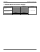
SiUS28-902_a Model Names and Power Supply 1.
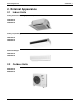
External Appearance SiUS28-902_a 2. External Appearance 2.1 Indoor Units Ceiling mounted cassette type (Multi flow) FCQ18PVJU FCQ24PVJU FCQ30PVJU Ceiling suspended type FHQ18PVJU FHQ24PVJU FHQ30PVJU Wall mounted type FAQ18PVJU FAQ24PVJU 2.
SiUS28-902_a Part 2 Specifications 1. Specifications..........................................................................................5 1.1 FCQ ......................................................................................................... 5 1.2 FHQ ......................................................................................................... 6 1.3 FAQ..........................................................................................................
Specifications SiUS28-902_a 1. Specifications 1.
SiUS28-902_a 1.
Specifications 1.3 SiUS28-902_a FAQ Wall Mounted Type Model Indoor unit FAQ18PVJU Outdoor unit RZQ18PVJU RZQ24PVJU 1 phase 60Hz 208-230V 18,000 20,000 1 phase 60Hz 208-230V 24,000 26,000 Power supply Cooling capacity ¹ Heating capacity ² Btu/h Btu/h FAQ24PVJU Indoor unit FAQ18PVJU FAQ24PVJU Color Dimensions White (3.0Y8.5/0.5) 11–3/8 × 41–3/8 × 9 (290 x 1050 x 230) Cross fin coil 2 × 14 × 18 2.29 QCL9686M Crossflow fan 43 500/400 Resin net (Washable) 31 (14) φ3/8 (9.
SiUS28-902_a Part 3 List of Electrical and Functional Parts 1. List of Electrical and Functional Parts .....................................................9 1.1 Outdoor Units ........................................................................................... 9 1.2 Indoor Units............................................................................................
List of Electrical and Functional Parts SiUS28-902_a 1. List of Electrical and Functional Parts 1.1 Outdoor Units Item Name Symbol Type Output Compressor Inverter Fan motor Motor Overcurrent relay Functional parts Electronic expansion Cooling valve Heating Four-way valve Solenoid valve (Hot gas) Solenoid valve (Injection) Pressure switch (INV.) Pressurerelated parts Thermistor 9 Fusible plug Pressure sensor (HP) Pressure sensor (LP) For outdoor air For discharge Main For suction 1 P.C.B.
SiUS28-902_a 1.2 List of Electrical and Functional Parts Indoor Units Model Parts Name Remote Controller Thermistors Others FCQ 18PVJU FCQ 24PVJU Wired Remote Controller BRC1D71 Wireless Remote Controller BRC7C812 Fan Motor Motors Symbol Capacitor, fan motor FCQ 30PVJU Remark Option 1φ90W 6P M1F Thermal Protector 266°F : OFF 176°F : ON C1 5.
SiUS28-902_a Part 4 Refrigerant Circuit 1. Refrigerant Circuit .................................................................................12 1.1 RZQ18·24·30PVJU ................................................................................ 12 2. Functional Parts Layout ........................................................................14 2.1 RZQ18·30PVJU .....................................................................................
SiUS28-902_a Refrigerant Circuit 1. Refrigerant Circuit 1.1 RZQ18·24·30PVJU No. in refrigerant Symbol system diagram Name Major Function A M1C Inverter compressor (INV.) Inverter compressor is operated on frequencies between 52 Hz and 177 Hz by using the inverter. 17 steps D M1F Inverter fan Since the system is of air heat exchanging type, the fan is operated at 8-step rotation speed by using the inverter.
Refrigerant Circuit SiUS28-902_a E T M - D G S J O S1NPH N S1NPL S1PH P A C : 3D062238B 13 Refrigerant Circuit
SiUS28-902_a Functional Parts Layout 2. Functional Parts Layout 2.
SiUS28-902_a Part 5 Function 1. Operation Mode ....................................................................................16 2. Basic Control.........................................................................................17 2.1 2.2 2.3 2.4 Normal Operation................................................................................... 17 Compressor PI Control .......................................................................... 18 Electronic Expansion Valve PI Control ...........
SiUS28-902_a Operation Mode 1.
Basic Control SiUS28-902_a 2. Basic Control 2.1 Normal Operation Cooling Operation Actuator Operation Remarks Compressor Compressor PI control Used for high pressure protection control, low pressure protection control, discharge pipe temperature protection control, and compressor operating frequency upper limit control with inverter protection control.
SiUS28-902_a 2.2 Basic Control Compressor PI Control Compressor PI Control Carries out the compressor capacity PI control to maintain Te at constant during cooling operation and Tc at constant during heating operation to ensure stable unit performance. [Cooling operation] Controls compressor capacity to adjust Te to achieve target value (TeS).
Basic Control 2.3 SiUS28-902_a Electronic Expansion Valve PI Control Main Electronic Expansion Valve EV1 Control Carries out the electronic expansion valve (Y1E) PI control to maintain the evaporator outlet superheated degree (SH) at constant during heating operation to make maximum use of the outdoor unit heat exchanger (evaporator).
SiUS28-902_a 2.4 Basic Control Cooling Operation Fan Control In cooling operation with low outdoor air temperature, this control is used to provide the adequate amount of circulation air with liquid pressure secured by high pressure control using outdoor unit fan.
Special Control SiUS28-902_a 3. Special Control 3.1 Startup Control On activation, the following control is performed to lighten the load of the compressor with liquid refrigerant located at the compressor at startup. Also, the position of the four-way valve is defined. 3.1.
SiUS28-902_a 3.2 Special Control Oil Return Operation Oil discharged by the compressor to the field piping is collected by the oil return operation. 3.2.1 Oil Return Operation in Cooling Operation [Conditions to start] The cooling oil-returning operation is started under the following conditions: Integrated amount of displaced oil Timer After the power is turned on, integrated operatingtime is 2 hours and subsequently every 8 hours.
Special Control SiUS28-902_a 3.2.2 Oil Return Operation in Heating Operation [Conditions to start] The heating oil-returning operation is started under the following conditions: Integrated amount of displaced oil Timer (After the power is turned on, integrated operating-time is 2 hours and subsequently every 8 hours.) In addition, the integrated amount of displaced oil is derived from Tc, Te, and the compressor load.
SiUS28-902_a 3.3 Special Control Defrosting Operation The defrost operation is performed to solve frost on the outdoor unit heat exchanger when heating, and the heating capacity is recovered. [Conditions to start] The defrost operation is started under the following conditions: Outdoor heat exchanger heat transfer co-efficiency Temperature of heat-exchange (Tb) Timer (2 hours at the minimum) In addition, outdoor heat-exchange co-efficiency is derived from Tc, Te, and the compressor load.
Special Control 3.4 SiUS28-902_a Pump-down Residual Operation When activating the compressor, if the liquid refrigerant remains in the heat-exchanger, the liquid enters into the compressor and dilutes oil therein resulting in a decrease of lubricity. Therefore, the pump-down residual operation is performed to collect the refrigerant in the heatexchanger when the compressor is down. 3.4.
SiUS28-902_a 3.5 Special Control Restart Standby Restart is not possible to prevent frequent power-on/off and to equalize pressure in the refrigerant system. Actuator Operation Remarks Compressor OFF ⎯ Outdoor unit fan Ta>86°F: STEP 4 Ta≤86°F: OFF ⎯ Four-way valve Keep former condition.
Special Control 3.6 SiUS28-902_a Stopping Operation When the system is down the actuator stops/clears all operations. 3.6.1 When System is in Stop Mode Actuator Operation Compressor OFF Outdoor unit fan OFF Four-way valve Keep former condition. Main electronic expansion valve (EV1) 0 pls Subcooling electronic expansion valve (EV2) 0 pls Hot gas bypass valve (SVP) OFF Receiver gas discharging valve (SVG) OFF Ending conditions Indoor unit thermostat is turned ON.
SiUS28-902_a 3.7 Special Control Pressure Equalization Prior to Startup Before activating the compressor, the activation load is lightened by equalization across the compressor. In addition, inverters turn on electricity and capacitors are charged. Actuator Operation Remarks Compressor OFF ⎯ Outdoor unit fan Cooling:OFF Heating:Ta>78.8°F; STEP 8, Ta≤78.8°F; OFF ⎯ Four-way valve Keep former condition.
Protection Control SiUS28-902_a 4. Protection Control 4.1 High Pressure Protection Control This high pressure protection control is used to prevent the activation of protection devices due to abnormal increase of high pressure and to protect compressors against the transient increase of high pressure. [In cooling operation] Pc>505 psi High pressure not limited Pc: HP pressure sensor detection value & or • INV.
SiUS28-902_a 4.2 Protection Control Low Pressure Protection Control This low pressure protection control is used to protect compressors against the transient decrease of low pressure. [In cooling operation] Low pressure not limited Pe<36 psi Pe: LP pressure sensor detection value Pe>57 psi Low pressure limited 57Hz Pe<10 psi Low pressure standby When occurring 3 times within 60 min., the malfunction code "E4" is output.
Protection Control 4.3 SiUS28-902_a Discharge Pipe Protection Control This discharge pipe protection control is used to protect the compressor internal temperature against a malfunction or transient increase of discharge pipe temperature. [INV. compressor] HTdi :Value of INV. compressor discharge pipe temperature (Tdi) compensated with outdoor air temperature Tp : Value of compressor port temperature calculated by Tc and Te, and suction superheated degree.
SiUS28-902_a 4.4 Protection Control Inverter Protection Control Inverter current protection control and inverter fin temperature control are performed to prevent tripping due to a malfunction, or transient inverter overcurrent, and fin temperature increase. [Inverter overcurrent protection control] Not limited & Inverter current >XA Limited •Inverter current ≤ XA •INV. upper limit frequency Tb≥77˚F X 13.7 Tb<77˚F 12.7 INV.
Other Control SiUS28-902_a 5. Other Control 5.1 Heating Operation Prohibition Heating operation is prohibited above 82°FDB outdoor air temperature.Outline of Control (Indoor Unit) 5.2 Drain Pump Control 1. The drain pump is controlled by the ON/OFF buttons (4 button (1) - (4) given in the figure below). 5.2.1 When the Float Switch is Tripped While the Cooling Thermostat is ON: ∗1.
SiUS28-902_a Other Control 5.2.3 When the Float Switch is Tripped During Heating Operation: During heating operation, if the float switch is not reset even after the 5 minutes operation, 5 seconds stop, 5 minutes operation cycle ends, operation continues until the switch is reset. 5.2.4 When the Float Switch is Tripped and “AF” is Displayed on the Remote Controller: *4. (Malfunction residual): If the float switch is tripped five times in succession, a drain malfunction is determined to have occurred.
Other Control 5.3 SiUS28-902_a Louver Control for Preventing Ceiling Dirt We have added a control feature that allows you to select the range of air direction and adjust it to prevent the ceiling surrounding the air discharge outlet of ceiling mounted cassette type units from being soiled.
SiUS28-902_a 5.4 Other Control Operation Range of Remote Controller Temperature Sensor Room temperature is controlled by the remote controller temperature sensor and return-air temperature sensor (unit-mounted temperature sensor) on the indoor unit. When the remote controller temperature sensor is set to Not Used in a field setting, the unit can be controlled only by unit mounted temperature sensor (or remote sensor).
Other Control 37 SiUS28-902_a Function
SiUS28-902_a Other Control Heating When heating, hot air rises to the top of the room which results in a lower temperature close to the floor where occupants are. This can cause the thermostat to turn off the unit before the lower part of the room reaches set-point temperature. To ensure a more evenly distributed temperature, position a Remote Sensor, at body level, in the occupied space or use the high ceiling installation service code.
Other Control 5.5 SiUS28-902_a Freeze Prevention Freeze Prevention by Off Cycle (Indoor Unit) When the temperature detected by the liquid pipe temperature thermistor (R2T) of the indoor unit heat exchanger drops too low, the unit enters freeze prevention operation in accordance with the following conditions, and is also set in accordance with the conditions given below. Conditions for starting freeze prevention: Temperature is 30°F or less for total of 40 min.
SiUS28-902_a 5.6 Other Control View of Operations of Swing Flaps Swing flaps work as following.
SiUS28-902_a Part 6 Test Operation 1. Test Operation ......................................................................................42 1.1 Procedure and Outline ........................................................................... 42 1.2 Operation when Power is Turned On..................................................... 45 2. Outdoor Unit P.C.B. Layout ..................................................................46 3. Field Setting .....................................................
SiUS28-902_a Test Operation 1. Test Operation 1.1 Procedure and Outline Follow the following procedure to conduct the initial test operation after installation. 1.1.1 Check Work Prior to Turn Power Supply On Check the below items.
Test Operation SiUS28-902_a 1.1.3 Check Operation * During check operation, position the front panel in full view so as to avoid incorrect readings.* Check operation is mandatory for normal unit operation. (When the check operation is not executed, alarm code "U3" will be displayed.) Press and hold the TEST button (BS4) on outdoor unit P.C.B. for 5 seconds. Check on operation ì ï ï ï ï ï ï ï ï î The test operation is started automatically.
SiUS28-902_a U4 UF UH Test Operation No power is supplied to the outdoor unit. Turn the power on for the outdoor unit. The shutoff valve of an outdoor unit is left closed. Open the gas-side shutoff valve and the liquid-side shutoff valve. If the right indoor unit piping and wiring are not properly connected to the outdoor unit. If the interunit wiring has not be connected or it has shorted. Make sure that the right indoor unit piping and wiring are properly connected to the outdoor unit.
Test Operation 1.2 SiUS28-902_a Operation when Power is Turned On 1.2.1 When Turning On Power First Time The unit cannot be run for up to 12 minutes to automatically set the master power and address (indoor-outdoor address, etc.). Status Outdoor unit Test lamp H2P .... Blinks Can also be set during operation described above. Indoor unit If ON button is pushed during operation described above, the “UH” malfunction indicator blinks. (Returns to normal when automatic setting is complete.) 1.2.
SiUS28-902_a Outdoor Unit P.C.B. Layout 2. Outdoor Unit P.C.B. Layout Outdoor unit P.C.B. DEMAND SLAVE MASTER IND L.N.O.
Field Setting SiUS28-902_a 3. Field Setting 3.1 Field Setting from Remote Controller Individual functions of indoor unit can be changed from the remote controller. At the time of installation or after service inspection / repair, make the local setting in accordance with the following description. An incorrect setting may cause malfunction. 3.1.1 Wired Remote Controller If optional accessories are mounted on the indoor unit, the indoor unit setting may have to be changed.
SiUS28-902_a Field Setting 3.1.2 Wireless Remote Controller - Indoor Unit BRC7C812 BRC7E83 BRC7E818 1. When in the normal mode, push the button for 4 seconds or more, and operation then enters the “field set mode.” 2. Select the desired “mode No.” with the button. 3. Pushing the button, select the first code No. 4. Pushing the button, select the second code No. 5. Push the timer button and check the settings. 6. Push the button to return to the normal mode.
Field Setting SiUS28-902_a 3.1.3 Simplified Remote Controller BRC2A71 6 13 2 1 3 5 H L F 7 4 8 9 11 10 12 BRC2A71 REMOTE CONTROLLER: NAME AND FUNCTION OF EACH SWITCH AND DISPLAY DISPLAY “ CONTROL) ON/OFF BUTTON Press the button and the system will start. Press the button again and the system will stop. OPERATION LAMP (RED) The lamp lights up during operation. Blinks in case of stop due to malfunction.
SiUS28-902_a Field Setting 3.1.4 Setting Contents and Code No. – VRV Unit Field Setting Contents and Code No. 0 Filter Contamination-Heavy/ Light (Setting for display time to clean air filter) (Sets display time to clean air filter to half when there is heavy filter contamination.
Field Setting SiUS28-902_a 3.1.5 Applicable Range of Field Setting Mode No. 10 (20) 12 (22) 13 (23) Setting Switch No.
SiUS28-902_a Field Setting 3.1.6 Detailed Explanation of Setting Modes Filter Sign Setting If switching the filter sign ON time, set as given in the table below. Set Time Filter Specs. Mode No. Setting Contamination Light Contamination Heavy Setting Switch No. 10(20) 0 Lighting interval of the filter sign (hours) Setting Position No. Standard 01 200 hrs. 2,500 hrs. Ultra Long Life Filter 10,000 hrs. 02 100 hrs. 1,250 hrs. 5,000 hrs.
Field Setting SiUS28-902_a Setting of Airflow Direction Adjustment Range Make the following air flow direction setting according to the respective purpose. Setting Table Mode No. First Code No. Second Code No. 01 Setting Upward (Draft prevention) 13 (23) 4 02 Standard Downward (Ceiling soiling prevention) 03 3.1.
SiUS28-902_a How to Select Operation Mode Example ON by remote controller (Unified ON by central remote controller) ↓ Rejection Field Setting Whether operation by remote controller will be possible or not for turning on/off, controlling temperature or setting operation mode is selected and decided by the operation mode shown in the right column of the following table.
Field Setting 3.2 SiUS28-902_a Field Setting from Outdoor Unit 3.2.1 Setting by push-button switches The following settings are made by pushbutton switches on P.C.B. LED display H1P H2P H3P H4P H5P H6P H7P h h k h h h h (Factory setting) BS1 BS2 BS3 BS4 BS5 MODE SET RETURN TEST RESET There are the following three setting modes. Setting mode 1 (H1P off) Initial status (when normal) : Also indicates during “abnormal”.
SiUS28-902_a Field Setting a. “Setting mode 1” Normally, “Setting mode 1” is set. In case of other status, push MODE button (BS1) one time and set to “Setting mode 1”. Display for malfunction/preparing/test-run ∗ The current state is displayed.
Field Setting SiUS28-902_a b. “Setting mode 2” No. Push and hold the MODE button (BS1) for 5 seconds and set to “Setting mode 2”. Push the SET button (BS2) and set the LED display to a setting item shown in the table on the right. ¯ Push the RETURN button (BS3) and decide on the item. (The present setting condition is blinking.) Push the SET button (BS2) and set to the setting condition you want.
SiUS28-902_a Field Setting k: ON h: OFF l: Blink Setting item display No.
Field Setting SiUS28-902_a k: ON h: OFF l: Blink c. Monitor mode No. To enter the monitor mode, push the MODE button (BS1) when in “Setting mode 1”. Push the SET button (BS2) and set the LED display to a setting item.
SiUS28-902_a 3.3 Field Setting Detail of Setting Mode 3.3.1 Cool / Heat Mode Switching The Cool / Heat Mode switching is carried out by remote controller fitted to indoor unit. This setting is not required for normal operation. (Factory set) 3.3.2 Setting of Low Noise Operation and Demand Operation Setting of Low Noise Operation By setting the low noise operation input to the outdoor unit P.C.B., you can lower operating noise by 2-3 dB.
Field Setting SiUS28-902_a Setting of Demand Operation By setting the demand input to the outdoor unit P.C.B., the power consumption of unit operation can be saved suppressing the compressor operating condition. [Demand setting] Setting Demand setting 1 Standard for upper limit of power consumption Approx. 60% Demand setting 2 (factory setting) Demand setting 3 Approx. 70% Approx. 80% The normal demand operation is carried out. (Use of the external control adapter for outdoor unit is not required.) 1.
SiUS28-902_a Field Setting : ON Setting No. Setting contents External low noise / Demand setting 22 Night-time low noise setting 26 27 29 30 32 Setting No.
Field Setting SiUS28-902_a 3.3.3 Setting of Refrigerant Recovery Mode When carrying out the refrigerant collection on site, fully open the respective expansion valves of indoor and outdoor units Both the outdoor unit and the indoor unit cannot be operated at this time. [Operation procedure] In setting mode 2 with units in stop mode, set Refrigerant Recovery / Vacuuming mode to ON. The respective expansion valve of indoor and outdoor units are fully opened.
SiUS28-902_a Field Setting 3.3.5 Check Operation To prevent any trouble in the period of installation at site, the system is provided with a test operation mode enabling checks for incorrect wiring, stop valve left closed, and automatic determination of of piping length. CHECK OPERATION FUNCTION LED display (H1P~H7P) (k:ON Unit stopping Step 1 Pressure equalizing Press the TEST button (BS4) for 5 seconds.
SiUS28-902_a Part 7 Troubleshooting 1. Symptom-based Troubleshooting .........................................................67 2. Troubleshooting by Remote Controller .................................................70 2.1 2.2 2.3 2.4 The INSPECTION / TEST Button .......................................................... 70 Self-diagnosis by Wired Remote Controller ........................................... 71 Self-diagnosis by Wireless Remote Controller.......................................
SiUS28-902_a 3.27 “JC” Outdoor Unit: Malfunction of Low Pressure Sensor ...................... 119 3.28 “L1” Outdoor Unit: Malfunction of P.C.B. .............................................. 121 3.29 “L4” Outdoor Unit: Malfunction of Inverter Radiating Fin Temperature Rise ............................................. 122 3.30 “L5” Outdoor Unit: Inverter Compressor Abnormal............................... 123 3.31 “L8” Outdoor Unit: Inverter Current Abnormal ...................................... 124 3.
Symptom-based Troubleshooting SiUS28-902_a 1. Symptom-based Troubleshooting 1 Symptom The system does not start operation at all. Supposed Cause Blowout of fuse(s) Countermeasure Turn Off the power supply and then replace the fuse(s). Cutout of breaker(s) • If the knob of any breaker is in its OFF position, turn ON the power supply. • If the knob of any circuit breaker is in its tripped position, do not turn ON the power supply.
SiUS28-902_a Symptom-based Troubleshooting Symptom 6 7 8 COOL-HEAT selection is disabled. The system conducts fan operation but not cooling or heating operation. The airflow rate is not reproduced according to the setting. 9 The airflow direction is not reproduced according to the setting. 10 A white mist comes out from the system. Troubleshooting Supposed Cause Countermeasure The remote controller displays "UNDER CENTRALIZED CONTROL".
Symptom-based Troubleshooting Symptom 11 The system produces sounds. SiUS28-902_a Supposed Cause Countermeasure Immediately after turning ON the power supply, indoor unit produces "ringing" sounds. "Hissing" sounds are continuously produced while in cooling or defrosting operation. These are operating sounds of Normal operation. the electronic expansion valve of This sound becomes low after a the indoor unit. lapse of approximately one minute.
SiUS28-902_a Troubleshooting by Remote Controller 2. Troubleshooting by Remote Controller 2.1 The INSPECTION / TEST Button The following modes can be selected by using the [Inspection/Test Operation] button on the remote control. Indoor unit settings can be made • Filter sign time • Airflow direction • Others Depress the Inspection/Test Operation button for more than 4 seconds. Local setting mode Service mode Depress the Inspection/Test Operation button for more than 4 seconds.
Troubleshooting by Remote Controller 2.2 SiUS28-902_a Self-diagnosis by Wired Remote Controller Explanation If operation stops due to malfunction, the remote controller’s operation LED blinks, and the malfunction code is displayed. (Even if stop operation is carried out, malfunction contents are displayed when the inspection mode is entered.) The malfunction code enables you to tell what kind of malfunction caused operation to stop. Refer to P.79 for malfunction code and malfunction contents.
SiUS28-902_a 2.3 Troubleshooting by Remote Controller Self-diagnosis by Wireless Remote Controller In the Case of BRC7C Type BRC7E Type BRC4C Type If equipment stops due to a malfunction, the operation indicating LED on the light reception section flashes. The malfunction code can be determined by following the procedure described below. The malfunction code is displayed when an operation error has occurred. In normal condition, the malfunction code of the last problem is displayed. 1.
Troubleshooting by Remote Controller SiUS28-902_a The lower digit of the code changes as shown below when the UP and DOWN buttons are pressed.
SiUS28-902_a Troubleshooting Troubleshooting by Remote Controller 74
Troubleshooting by Remote Controller 2.4 SiUS28-902_a Operation of the Remote Controller’s Inspection / Test Operation Button 0 L0 Unit Malfunction code Inspection Malfunction code blinks when a malfunction occurs. Normal display (No display) Inspection/test operation Unit Malfunction code Inspection Push the button. 0 L0 Inspection mode Inspection/test operation Example of capacity code display 0 7 1... Capacity code F... Indoor unit system code C... Indoor unit type code J...
SiUS28-902_a 2.5 Troubleshooting by Remote Controller Remote Controller Service Mode How to Enter the Service Mode Service Mode Operation Method 1. Select the mode No. Set the desired mode No. with the button. (For wireless remote controller, Mode 43 only can be set.) 2. Select the unit No. (For group control only) Select the indoor unit No. to be set with the time mode . (For wireless remote controller, button.) 3. Make the settings required for each mode.
Troubleshooting by Remote Controller Mode No 40 Function Malfunction hysteresis display SiUS28-902_a Contents and operation method Remote controller display example Display malfunction history. The history No. can be changed with the button. Unit 1 Malfunction code 2-U4 40 Malfunction code History No: 1 - 9 1: Latest 41 Display of sensor and address data Display various types of data. Select the data to be displayed with the button. Sensor data 0: Thermostat sensor in remote controller.
SiUS28-902_a 2.6 Troubleshooting by Remote Controller Remote Controller Self-Diagnosis Function The remote controller switches are equipped with a self-diagnosis function so that more appropriate maintenance can be carried out. If a malfunction occurs during operation, the operation lamp, malfunction code and display of malfunctioning unit No. let you know the contents and location of the malfunction.
Troubleshooting by Remote Controller SiUS28-902_a Malfunction Operation Inspection code lamp display Indoor Unit Outdoor Unit 79 Unit No. k: ON Malfunction contents h: OFF l: Blink Page Referred A0 A1 l l l l l l Error of external protection device P.C.B.
SiUS28-902_a Troubleshooting by Remote Controller k: ON Malfunction Operation Inspection code lamp display Outdoor Unit LA l l System Centralized Remote Controller and Schedule Timer Heat Reclaim Ventilation Unit No. h: OFF Malfunction contents l Malfunction of power unit LC l l l P4 k l k Malfunction of transmission between inverter and control P.C.B.
Troubleshooting by Remote Controller SiUS28-902_a Malfunction code indication by outdoor unit P.C.B. Contents of malfunction To enter the monitor mode, push the MODE (BS1) button when in “Setting mode 1”. Push the SET (BS2) button and set the LED display to a setting item. In-phase malfunction of DIII-Net Detection of DIII-Net E1 Abnormal discharge pressure HPS activated E3 Abnormal suction pressure Abnormal Pe E4 Compressor lock Detection of INV.
SiUS28-902_a Troubleshooting by Remote Controller k: ON h: OFF l:Blink Confirmation of malfunction 1 Confirmation of malfunction 2 Confirmation of malfunction 3 Confirmation of malfunction 4 Malfunction code H1P H2P H3P H4P H5P H6P H7P H1P H2P H3P H4P H5P H6P H7P H1P H2P H3P H4P H5P H6P H7P H1P H2P H3P H4P H5P H6P H7P l l l l l l l h h h h h l l h h l l l h h h l h h l h h l l h l l l l l l l l l l l l l l h h h h l h l l l l h l J5 l h l h l J6 l h l l h JA l l l l l l l l l l
Troubleshooting by Remote Controller SiUS28-902_a Contents of malfunction To enter the monitor mode, push the MODE (BS1) button when in “Setting mode 1”.
SiUS28-902_a Troubleshooting by Remote Controller k: ON h: OFF l:Blink Confirmation of malfunction 1 Confirmation of malfunction 2 Confirmation of malfunction 3 Confirmation of malfunction 4 Malfunction code H1P H2P H3P H4P H5P H6P H7P H1P H2P H3P H4P H5P H6P H7P H1P H2P H3P H4P H5P H6P H7P H1P H2P H3P H4P H5P H6P H7P P4 l l h h h l h l h h l h h h h l h h ∗1 U0 l l h h l U2 l l h h h h h l h h U3 l h h l l U4 l h l h h UH l l l l h l l l l l UF Display of contents of mal
Troubleshooting by Indication on the Remote Controller SiUS28-902_a 3. Troubleshooting by Indication on the Remote Controller 3.1 “A0” Indoor Unit: Error of External Protection Device Remote A0 Controller Display Applicable Models All indoor unit models Method of Malfunction Detection Malfunction Decision Conditions Supposed Causes Actuation of external protection device Improper field set Defect of indoor unit P.C.B.
SiUS28-902_a 3.2 Troubleshooting by Indication on the Remote Controller “A1 ” Indoor Unit: P.C.B. Defect Remote Controller Display A1 Applicable Models All indoor unit models Method of Malfunction Detection Check data from E²PROM. Malfunction Decision Conditions When data could not be correctly received from the E²PROM E²PROM : Type of nonvolatile memory. Maintains memory contents even when the power supply is turned off. Supposed Causes Defect of indoor unit P.C.B.
Troubleshooting by Indication on the Remote Controller 3.3 “A3 ” Indoor Unit: Malfunction of Drain Level Control System (S1L) Remote Controller Display A3 Applicable Models FCQ, FHQ (Option), FAQ (Option) Method of Malfunction Detection Float switch OFF detection Malfunction Decision Conditions When rise of water level is not a condition and the float switch goes OFF.
SiUS28-902_a Troubleshooting by Indication on the Remote Controller Troubleshooting Caution Be sure to turn off the power switch before connecting or disconnecting the connector or parts could be damaged. Is power supply 208~230V provided? NO Provide 208~230V power supply. YES The float switch is connected to X8A (or X15A) of the indoor unit P.C.B.
Troubleshooting by Indication on the Remote Controller 3.
SiUS28-902_a 3.5 Troubleshooting by Indication on the Remote Controller “A7 ” Indoor Unit: Malfunction of Louver Motor (M1S) Remote Controller Display A7 Applicable Models FCQ, FHQ, FAQ Method of Malfunction Detection Utilizes ON/OFF of the limit switch when the motor turns. Malfunction Decision Conditions When ON/OFF of the microswitch for positioning cannot be reversed even though the louver motor is energized for a specified amount of time (about 30 seconds).
Troubleshooting by Indication on the Remote Controller SiUS28-902_a Troubleshooting Caution Be sure to turn off the power switch before connecting or disconnecting the connector, or parts could be damaged. Is power supply 208~230V provided? NO Provide 208~230V power supply. YES Indoor unit is a model equipped with a louver function NO Replace the indoor unit P.C.B. YES The louver motor works when the power supply is turned off and then back on.
SiUS28-902_a 3.6 Troubleshooting by Indication on the Remote Controller “A9 ” Indoor Unit: Malfunction of Moving Part of Electronic Expansion Valve (Y1E) Remote Controller Display Applicable Models A9 All indoor unit models Method of Malfunction Detection Malfunction Decision Conditions Supposed Causes Malfunction of moving part of electronic expansion valve Defect of indoor unit P.C.B.
Troubleshooting by Indication on the Remote Controller SiUS28-902_a ∗1: Coil check method for the moving part of the electronic expansion valve Disconnect the electronic expansion valve from the P.C.B. and check the continuity between the connector pins. (Normal) Pin No. 1. White 2. Yellow 3. Orange 4. Blue 5. Red 1. White 2. Yellow 3. Orange 4. Blue 5. Red 6. Brown × Approx. 300Ω × × Approx. 150Ω × × Approx. 300Ω × Approx. 150Ω × Approx. 150Ω × Approx. 150Ω × 6.
SiUS28-902_a 3.7 Troubleshooting by Indication on the Remote Controller “AF ” Indoor Unit: Drain Level above Limit Remote Controller Display AF Applicable Models FCQ Method of Malfunction Detection Water leakage is detected based on float switch ON/OFF operation while the compressor is in non-operation. Malfunction Decision Conditions When the float switch changes from ON to OFF while the compressor is in non-operation.
Troubleshooting by Indication on the Remote Controller 3.8 SiUS28-902_a “AJ ” Indoor Unit: Malfunction of Capacity Determination Device Remote controller display AJ Applicable Models All indoor unit models Method of Malfunction Detection Capacity is determined according to resistance of the capacity setting adaptor and the memory inside the IC memory on the indoor unit P.C.B., and whether the value is normal or abnormal is determined. Malfunction Decision Conditions Operation and: 1.
SiUS28-902_a 3.9 Troubleshooting by Indication on the Remote Controller “C4 ” Indoor Unit: Malfunction of Thermistor (R2T) for Heat Exchanger Remote Controller Display C4 Applicable Models All indoor unit models Method of Malfunction Detection Malfunction detection is carried out by temperature detected by heat exchanger thermistor. Malfunction Decision Conditions When the heat exchanger thermistor becomes disconnected or shorted while the unit is running.
Troubleshooting by Indication on the Remote Controller SiUS28-902_a 3.10 “C5 ” Indoor Unit: Malfunction of Thermistor (R3T) for Gas Pipes Remote Controller Display C5 Applicable Models All indoor unit models Method of Malfunction Detection Malfunction detection is carried out by temperature detected by gas pipe thermistor. Malfunction Decision Conditions When the gas pipe thermistor becomes disconnected or shorted while the unit is running.
SiUS28-902_a Troubleshooting by Indication on the Remote Controller 3.11 “C9 ” Indoor Unit: Malfunction of Thermistor (R1T) for Suction Air Remote Controller Display C9 Applicable Models AII indoor unit models Method of Malfunction Detection Malfunction detection is carried out by temperature detected by suction air temperature thermistor. Malfunction Decision Conditions When the suction air temperature thermistor becomes disconnected or shorted while the unit is running.
Troubleshooting by Indication on the Remote Controller SiUS28-902_a 3.12 “CA ” Indoor Unit: Malfunction of Thermistor for Discharge Air Remote Controller Display CA Applicable Models AII indoor unit models Method of Malfunction Detection Malfunction detection is carried out by temperature detected by discharge air temperature thermistor. Malfunction Decision Conditions When the discharge air temperature thermistor becomes disconnected or shorted while the unit is running.
SiUS28-902_a Troubleshooting by Indication on the Remote Controller 3.13 “CJ ” Indoor Unit: Malfunction of Thermostat Sensor in Remote Controller CJ Remote Controller Display Applicable Models AII indoor unit models Method of Malfunction Detection Malfunction detection is carried out by temperature detected by remote controller air temperature thermistor.
Troubleshooting by Indication on the Remote Controller SiUS28-902_a 3.14 “E1 ” Outdoor Unit: P.C.B. Defect Remote Controller Display E1 Applicable Models RZQ18~30PVJU Method of Malfunction Detection Check data from E²PROM Malfunction Decision Conditions When data could not be correctly received from the E²PROM E²PROM : Type of nonvolatile memory. Maintains memory contents even when the power supply is turned off. Supposed Causes Defect of outdoor unit P.C.B.
SiUS28-902_a Troubleshooting by Indication on the Remote Controller 3.15 “E3 ” Outdoor Unit: Actuation of High Pressure Switch Remote Controller Display E3 Applicable Models RZQ18~30PVJU Method of Malfunction Detection Abnormality is detected when the contact of the high pressure protection switch opens. Malfunction Decision Conditions Error is generated when the HPS activation count reaches the number specific to the operation mode.
Troubleshooting by Indication on the Remote Controller SiUS28-902_a Troubleshooting Caution Be sure to turn off the power switch before connecting or disconnecting the connector, or parts could be damaged. Check for the points shown below. Is the stop valve open? Is the HPS connector properly connected to the main P.C.B.? Does the high pressure switch have continuity? Are the three points above OK? NO Rectify defective points, if any.
SiUS28-902_a Troubleshooting by Indication on the Remote Controller 3.16 “E4 ” Outdoor Unit: Actuation of Low Pressure Sensor Remote Controller Display E4 Applicable Models RZQ18~30PVJU Method of Malfunction Detection Abnormality is detected by the pressure value with the low pressure sensor. Malfunction Decision Conditions Error is generated when the low pressure is dropped under specific pressure.
Troubleshooting by Indication on the Remote Controller SiUS28-902_a Troubleshooting Caution Be sure to turn off the power switch before connecting or disconnecting the connector, or parts could be damaged. NO Is the stop valve open? Open the stop valve. YES Mount a pressure gauge on the low-pressure service port. Connect the Service Checker. Reset the operation using the remote controller, and then restart the operation. Are the characteristics of the low pressure sensor normal? (See *1.
SiUS28-902_a Troubleshooting by Indication on the Remote Controller 3.17 “E5 ” Inverter Compressor Motor Lock Remote Controller Display E5 Applicable Models RZQ18~30PVJU Method of Malfunction Detection Inverter P.C.B. takes the position signal from UVW line connected between the inverter and compressor, and the malfunction is detected when any abnormality is observed in the phasecurrent waveform.
Troubleshooting by Indication on the Remote Controller SiUS28-902_a Troubleshooting Caution Be sure to turn off the power switch before connecting or disconnecting the connector, or parts could be damaged. Check the installation conditions. Is the stop valve open? NO Open the stop valve. YES Is the UVW wiring normal? NO Connect correctly. YES Is high differential pressure starting? (72psi or more) YES Remedy the cause. NO Check and see whether compressor is short-circuited or grounded.
SiUS28-902_a Troubleshooting by Indication on the Remote Controller 3.18 “E7 ” Malfunction of Outdoor Unit Fan Motor Remote Controller Display E7 Applicable Models RZQ18~30PVJU Method of Malfunction Detection Malfunction of fan motor system is detected according to the fan speed detected by hall IC when the fan motor runs.
Troubleshooting by Indication on the Remote Controller SiUS28-902_a 3.19 “E9 ” Outdoor Unit: Malfunction of Moving Part of Electronic Expansion Valve (Y1E) Remote Controller Display E9 Applicable Models RZQ18~30PVJU Method of Malfunction Detection Check disconnection of connector Check continuity of expansion valve coil Malfunction Decision Conditions Error is generated under no common power supply when the power is on.
SiUS28-902_a Troubleshooting by Indication on the Remote Controller Troubleshooting Caution Be sure to turn off the power switch before connecting or disconnecting the connector, or parts could be damaged. Turn power supply off, and turn power supply on again. Return to normal? YES External factor other than malfunction (for example, noise etc.). NO Electronic expansion valve is connected to X21A and X22A of outdoor unit P.C.B. (A1P). NO After connecting, turn the power off and then back on again.
Troubleshooting by Indication on the Remote Controller SiUS28-902_a 3.20 “F3 ” Outdoor Unit: Abnormal Discharge Pipe Temperature Remote Controller Display F3 Applicable Models RZQ18~30PVJU Method of Malfunction Detection Abnormality is detected according to the temperature detected by the discharge pipe temperature sensor.
SiUS28-902_a Troubleshooting by Indication on the Remote Controller 3.21 “F6 ” Outdoor Unit: Refrigerant Overcharged Remote Controller Display F6 Applicable Models RZQ18~30PVJU Method of Malfunction Detection Excessive charging of refrigerant is detected by using the heat exchanging deicer temperature during a check operation. Malfunction Decision Conditions When the amount of refrigerant, which is calculated by using the heat exchanging deicer temperature during a check run, exceeds the standard.
Troubleshooting by Indication on the Remote Controller SiUS28-902_a 3.22 “H9 ” Outdoor Unit: Malfunction of Thermistor (R1T) for Outdoor Air Remote Controller Display H9 Applicable Models RZQ18~30PVJU Method of Malfunction Detection Malfunction is detected from the temperature detected by the outdoor air thermistor. Malfunction Decision Conditions When the outside air temperature thermistor has short circuit or open circuit.
SiUS28-902_a Troubleshooting by Indication on the Remote Controller 3.23 “J3 ” Outdoor Unit: Malfunction of Discharge Pipe Thermistor (R2T) Remote Controller Display J3 Applicable Models RZQ18~30PVJU Method of Malfunction Detection Malfunction is detected from the temperature detected by discharge pipe temperature thermistor. Malfunction Decision Conditions When a short circuit or an open circuit in the discharge pipe temperature thermistor is detected.
Troubleshooting by Indication on the Remote Controller SiUS28-902_a 3.24 “J5 ” Outdoor Unit: Malfunction of Thermistor (R3T, R5T) for Suction Pipe 1, 2 Remote Controller Display J5 Applicable Models RZQ18~30PVJU Method of Malfunction Detection Malfunction is detected from the temperature detected by the thermistor for suction pipe 1, 2. Malfunction Decision Conditions When a short circuit or an open circuit in the thermistor for suction pipe 1, 2 are detected.
SiUS28-902_a Troubleshooting by Indication on the Remote Controller 3.25 “J6 ” Outdoor Unit: Malfunction of Thermistor (R4T) for Outdoor Unit Heat Exchanger Remote Controller Display J6 Applicable Models RZQ18~30PVJU Method of Malfunction Detection Malfunction is detected from the temperature detected by the heat exchanger thermistor. Malfunction Decision Conditions When a short circuit or an open circuit in the heat exchange thermistor is detected.
Troubleshooting by Indication on the Remote Controller SiUS28-902_a 3.26 “JA ” Outdoor Unit: Malfunction of High Pressure Sensor Remote Controller Display JA Applicable Models RZQ18~30PVJU Method of Malfunction Detection Malfunction is detected from the pressure detected by the high pressure sensor. Malfunction Decision Conditions When the high pressure sensor is short circuit or open circuit.
SiUS28-902_a Troubleshooting by Indication on the Remote Controller Troubleshooting Caution Be sure to turn off the power switch before connecting or disconnecting the connector, or parts could be damaged. The high pressure sensor is connected to X17A of outdoor unit P.C.B. (A1P). NO Connect the high pressure sensor and turn on again. YES The relationship between the *1 VH and high pressure YES is normal (see *2) when voltage is measured between X17A pins (1) and (3) of outdoor unit P.C.B.
Troubleshooting by Indication on the Remote Controller SiUS28-902_a 3.27 “JC ” Outdoor Unit: Malfunction of Low Pressure Sensor Remote Controller Display JC Applicable Models RZQ18~30PVJU Method of Malfunction Detection Malfunction is detected from pressure detected by low pressure sensor. Malfunction Decision Conditions When the low pressure sensor is short circuit or open circuit. Supposed Causes Defect of low pressure sensor Connection of high pressure sensor with wrong connection.
SiUS28-902_a Troubleshooting by Indication on the Remote Controller Troubleshooting Caution Be sure to turn off the power switch before connecting or disconnecting the connector, or parts could be damaged. The low pressure sensor is connected to X18A (blue) of outdoor unit P.C.B. (A1P). NO Connect the low pressure sensor property and restart system. YES The relationship between the *1 VL and low pressure is normal (see *2) when voltage is measured between X18A pins (2) and (3) of outdoor unit P.C.B.
Troubleshooting by Indication on the Remote Controller SiUS28-902_a 3.28 “L1 ” Outdoor Unit: Malfunction of P.C.B. Remote Controller Display L1 Applicable Models RZQ18~30PVJU Method of Malfunction Detection Detect malfunctions by current value during waveform output before compressor startup. Detect malfunctions by current sensor value during synchronized operation at the time of startup. Detect malfunctions using an SP-PAM series capacitor overvoltage sensor.
SiUS28-902_a Troubleshooting by Indication on the Remote Controller 3.29 “L4 ” Outdoor Unit: Malfunction of Inverter Radiating Fin Temperature Rise Remote Controller Display L4 Applicable Models RZQ18~30PVJU Method of Malfunction Detection Fin temperature is detected by the thermistor of the radiation fin. Malfunction Decision Conditions When the temperature of the inverter radiation fin increases above 180°F.
Troubleshooting by Indication on the Remote Controller SiUS28-902_a 3.30 “L5 ” Outdoor Unit: Inverter Compressor Abnormal Remote Controller Display L5 Applicable Models RZQ18~30PVJU Method of Malfunction Detection Malfunction is detected from current flowing in the power transistor. Malfunction Decision Conditions When an excessive current flows in the power transistor. (Instantaneous overcurrent also causes activation.
SiUS28-902_a Troubleshooting by Indication on the Remote Controller 3.31 “L8 ” Outdoor Unit: Inverter Current Abnormal Remote Controller Display L8 Applicable Models RZQ18~30PVJU Method of Malfunction Detection Malfunction is detected by current flowing in the power transistor. Malfunction Decision Conditions When overload in the compressor is detected. Supposed Causes Compressor overload Compressor coil disconnected Defect of outdoor unit P.C.B.
Troubleshooting by Indication on the Remote Controller SiUS28-902_a Troubleshooting Caution Be sure to turn off the power switch before connecting or disconnecting the connector, or parts could be damaged. Output current check The secondary current of the inverter is higher than X16.8A, 260sec. for each phase. YES Compressor overload Inspection of the compressor and refrigerant system is required. NO Compressor inspection The compressor's coil is disconnected. YES Replace the compressor.
SiUS28-902_a Troubleshooting by Indication on the Remote Controller 3.32 “L9 ” Outdoor Unit: Inverter Start up Error Remote Controller Display L9 Applicable Models RZQ18~30PVJU Method of Malfunction Detection Malfunction is detected from current flowing in the power transistor. Malfunction Decision Conditions When overload in the compressor is detected during startup Supposed Causes Defect of compressor‘ Pressure differential start Defect of outdoor unit P.C.B.
Troubleshooting by Indication on the Remote Controller SiUS28-902_a 3.33 “LC ” Outdoor Unit: Malfunction of Transmission between Inverter and Control P.C.B. Remote Controller Display LC Applicable Models RZQ18~30PVJU Method of Malfunction Detection Check the communication state between inverter P.C.B. and control P.C.B. by micro-computer. Malfunction Decision Conditions When the correct communication is not conducted in certain period.
SiUS28-902_a Troubleshooting by Indication on the Remote Controller 3.34 “P4 ” Outdoor Unit: Malfunction of Inverter Radiating Fin Temperature Rise Sensor Remote Controller Display P4 Applicable Models RZQ18~30PVJU Method of Malfunction Detection Resistance of radiation fin thermistor is detected when the compressor is not operating. Malfunction Decision Conditions When the resistance value of thermistor becomes a value equivalent to open or short circuited status.
Troubleshooting by Indication on the Remote Controller SiUS28-902_a 3.35 “U0 ” Outdoor Unit: Low Pressure Drop Due to Refrigerant Shortage or Electronic Expansion Valve Failure Remote Controller Display U0 Applicable Models RZQ18~30PVJU Method of Malfunction Detection Short of gas malfunction is detected by discharge pipe temperature thermistor and low pressure saturation temperature. Malfunction Decision Conditions Microcomputer judge and detect if the system is short of refrigerant.
SiUS28-902_a Troubleshooting by Indication on the Remote Controller Troubleshooting Caution Be sure to turn off the power switch before connecting or disconnecting the connector, or parts could be damaged. Cooling YES NO The suction pipe1 temp. minus low pressure saturation temp. is 36 °F or higher. Low pressure is 36psi or less. NO The voltage of X18A pins (2) and (3) on main outdoor unit P.C.B. (A1P) is 1.0 VDC or less.
Troubleshooting by Indication on the Remote Controller SiUS28-902_a 3.36 “U2 ” Power Supply Insufficient or Instantaneous Failure Remote Controller Display U2 Applicable Models RZQ18~30PVJU Method of Malfunction Detection Detection of voltage of main circuit capacitor built in the inverter and power supply voltage. Malfunction Decision Conditions When the abnormal voltage of main circuit capacitor built in the inverter and abnormal power supply voltage are detected.
SiUS28-902_a Troubleshooting by Indication on the Remote Controller Troubleshooting Caution Be sure to turn off the power switch before connecting or disconnecting the connector, or parts could be damaged. Is the power supply voltage 208~230V ±10%? NO Correct power supply. YES CHECK (4P.158) Check the inverter power transistor. YES Has the power transistor malfunctioned? NO CHECK (P.158) 3 Is the resistance above standard value? NO Replace the inverter P.C.B. Observe the conditions of the P.C.B.
Troubleshooting by Indication on the Remote Controller SiUS28-902_a 3.37 “U3 ” Check Operation not Executed Remote Controller Display U3 Applicable Models RZQ18~30PVJU Method of Malfunction Detection Check operation is executed or not Malfunction Decision Conditions Malfunction is decided when the unit starts operation without check operation. Supposed Causes Check operation is not executed.
SiUS28-902_a Troubleshooting by Indication on the Remote Controller 3.38 “U4 ” Malfunction of Transmission between Indoor Units and Outdoor Units Remote Controller Display U4 Applicable Models AII indoor unit models RZQ18~30PVJU Method of Malfunction Detection Microcomputer checks if transmission between indoor and outdoor units is normal. Malfunction Decision Conditions When transmission is not carried out normally for a certain amount of time.
Troubleshooting by Indication on the Remote Controller SiUS28-902_a Troubleshooting Caution Be sure to turn off the power switch before connecting or disconnecting the connector, or parts could be damaged. Has the indoor or outdoor unit P.C.B. been replaced, or has the indoor - outdoor or outdoor - outdoor unit transmission wiring been modified? YES Push and hold the RESET button on the master outdoor unit P.C.B. for 5 seconds. * The unit will not operate for up to 12 minutes.
SiUS28-902_a Troubleshooting by Indication on the Remote Controller 3.39 “U5 ” Malfunction of Transmission between Remote Controller and Indoor Unit Remote Controller Display U5 Applicable Models AII indoor unit models Method of Malfunction Detection In case of controlling with 2-remote controller, check the system using microcomputer is signal transmission between indoor unit and remote controller (main and sub) is normal.
Troubleshooting by Indication on the Remote Controller SiUS28-902_a 3.40 “U8 ” Malfunction of Transmission between Main and Sub Remote Controllers Remote Controller Display U8 Applicable Models AII indoor unit models Method of Malfunction Detection In case of controlling with 2-remote controller, check the system using the microcomputer if signal transmission between indoor unit and remote controller (main and sub) is normal.
SiUS28-902_a Troubleshooting by Indication on the Remote Controller 3.41 “UE ” Malfunction of Transmission between Centralized Remote Controller and Indoor Unit Remote Controller Display UE Applicable Models AII indoor unit models Centralized controller Method of Malfunction Detection Microcomputer checks if transmission between indoor unit and centralized remote controller is normal.
Troubleshooting by Indication on the Remote Controller SiUS28-902_a Troubleshooting Caution Be sure to turn off the power switch before connecting or disconnecting the connector, or parts could be damaged. Has an indoor unit once connected been removed or its address changed? YES Reset power supply simultaneously for all optional controllers for centralized control. NO Is the power supply turned on for indoor units displaying malfunction? NO Turn indoor unit's power supply.
SiUS28-902_a Troubleshooting by Indication on the Remote Controller 3.42 “UF ” System is not Set yet UF Remote Controller Display Applicable Models All models of indoor units RZQ18~30PVJU Method of Malfunction Detection On check operation, the number of indoor units in terms of transmission is not corresponding to that of indoor units that have made changes in temperature.
Troubleshooting by Indication on the Remote Controller SiUS28-902_a 3.43 “UH ” Malfunction of System, Refrigerant System Address Undefined Remote Controller Display Applicable Models UH AII indoor unit models RZQ18~30PVJU Method of Malfunction Detection Malfunction Decision Conditions Supposed Causes 141 Improper connection of transmission wiring between outdoor unit and outdoor unit outside control adaptor Defect of indoor unit P.C.B. Defect of outdoor unit P.C.B.
SiUS28-902_a Troubleshooting by Indication on the Remote Controller Troubleshooting Caution Be sure to turn off the power switch before connecting or disconnecting the connector, or parts could be damaged. Is electricity being introduce for the first time after installation after an indoor or outdoor unit P.C.B.
Troubleshooting by Indication on the Centralized Remote Controller SiUS28-902_a 4. Troubleshooting by Indication on the Centralized Remote Controller 4.1 “UE ” Malfunction of Transmission between Centralized Remote Controller and Indoor Unit Remote Controller Display UE Applicable Models AII indoor unit models Centralized Remote Controller Method of Malfunction Detection Microcomputer checks if transmission between indoor unit and centralized remote controller is normal.
SiUS28-902_a Troubleshooting by Indication on the Centralized Remote Controller Troubleshooting Caution Be sure to turn off the power switch before connecting or disconnecting the connector, or parts could be damaged. Has an indoor unit once connected been removed or its address changed? YES Reset power supply simultaneously for all optional controllers for centralized control. NO Is the power supply turned on for indoor units displaying malfunction? NO Turn indoor unit's power supply.
Troubleshooting by Indication on the Centralized Remote Controller 4.2 SiUS28-902_a “M1 ” P.C.B. Defect Remote Controller Display Applicable Models M1 Centralized remote controller Method of Malfunction Detection Malfunction Decision Conditions Supposed Causes Defect of centralized remote controller P.C.B. Troubleshooting Replace the centralized remote controller P.C.B.
SiUS28-902_a 4.3 Troubleshooting by Indication on the Centralized Remote Controller “M8 ” Malfunction of Transmission between Optional Controllers for Centralized Control Remote Controller Display Applicable Models M8 Centralized remote controller Method of Malfunction Detection Malfunction Decision Conditions Supposed Causes Malfunction of transmission between optional controllers for centralized control Defect of P.C.B.
Troubleshooting by Indication on the Centralized Remote Controller 4.4 SiUS28-902_a “MA ” Improper Combination of Optional Controllers for Centralized Control Remote Controller Display Applicable Models MA Centralized remote controller Method of Malfunction Detection Malfunction Decision Conditions Supposed Causes 147 Improper combination of optional controllers for centralized control More than one master controller is connected Defect of P.C.B.
SiUS28-902_a Troubleshooting by Indication on the Centralized Remote Controller Troubleshooting Caution Be sure to turn off the power switch before connecting or disconnecting the connector, or parts could be damaged. Is the wiring adaptor for electrical appendices connected? YES Cannot be used in combination with a wiring adaptor for electrical appendices.
Troubleshooting by Indication on the Centralized Remote Controller 4.5 SiUS28-902_a “MC ” Address Duplication, Improper Setting Remote Controller Display Applicable Models MC Centralized remote controller Method of Malfunction Detection Malfunction Decision Conditions Supposed Causes Address duplication of centralized remote controller Troubleshooting Caution Be sure to turn off the power switch before connecting or disconnecting the connector, or parts could be damaged.
SiUS28-902_a Troubleshooting by Indication on the Unified ON/OFF Controller 5. Troubleshooting by Indication on the Unified ON/ OFF Controller 5.
Troubleshooting by Indication on the Unified ON/OFF Controller SiUS28-902_a Troubleshooting Caution Be sure to turn off the power switch before connecting or disconnecting the connector, or parts could be damaged. Is a malfunction code displayed on the remote controller? YES Diagnose the cause with the air conditioner's failure diagnosis manual.
SiUS28-902_a 5.
Troubleshooting by Indication on the Unified ON/OFF Controller SiUS28-902_a Troubleshooting Be sure to turn off the power switch before connecting or disconnecting the connector, or parts could be damaged. Caution Has a once connected optional controller for centralized control been disconnected or its address changed? YES Reset power supply simultaneously for all optional controllers for centralized control.
SiUS28-902_a Troubleshooting by Indication on the Unified ON/OFF Controller A Is the wiring adaptor for electrical appendices connected? YES NO Is a schedule timer connected? YES Is a data station connected? NO YES NO Is a parallel interface connected? YES NO Is the schedule timer's individual/combined connector connected? NO Are there two or more optional controllers for centralized control connected with the connector for setting master control? YES NO Reset the power supply for all optio
Troubleshooting by Indication on the Unified ON/OFF Controller 5.3 SiUS28-902_a Display “Under Host Computer Integrate Control” Blinks (Repeats Double Blink) Remote Controller Display “Under host computer integrated control” (Repeats double blink) Applicable Models Unified ON/OFF controller Method of Malfunction Detection Malfunction Decision Conditions Supposed Causes Central control address (group No.) is not set for indoor unit.
SiUS28-902_a Troubleshooting by Indication on the Unified ON/OFF Controller CHECK 1 Check for causes of rise in high pressure Referring to the Fault Tree Analysis (FTA) shown below, probe the faulty points. Local pressure rise High pipe resistance [In cooling] If the outdoor unit electronic expansion valve is throttled: (See *1.) Faulty outdoor unit electronic expansion valve A temperature difference in excess of 50°F Stop valve closed ¬Check to be sure the stop valve is open.
Troubleshooting by Indication on the Unified ON/OFF Controller SiUS28-902_a CHECK 2 Check for causes of drop in low pressure Referring to the Fault Tree Analysis (FTA) shown below, probe the faulty points. [In cooling] (See *1.) Faulty low pressure control Abnormally low low-pressure (Low evaporating temperature) [In both cooling and heating] (See *2.) [In cooling] If the indoor unit electronic expansion valve is throttled too much: (See *3.
SiUS28-902_a Troubleshooting by Indication on the Unified ON/OFF Controller CHECK 3 Check for Fan Motor Connector (1) Turn the power supply off. (2) With the fan motor connector disconnected, measure the resistance between each pin, then make sure that the resistance is more than the value mentioned in the following table.
SiUS28-902_a Part 8 Appendix 1. Piping Diagrams .................................................................................160 1.1 Outdoor Unit ........................................................................................ 160 1.2 Indoor Unit .......................................................................................... 161 2. Wiring Diagrams for Reference ..........................................................162 2.1 Outdoor Unit ............................................
SiUS28-902_a Piping Diagrams 1. Piping Diagrams 1.
Piping Diagrams 1.
X1M L1L2 A2P L1R A1P A2P BS1~5 C1~3 DS1 F1U F6U H1P~8P(A2P) HAP Appendix 3D062307B 2.1 BRN RED ORG YLW INDOOR (F1)(F2) NOTE)3 PRINTED CIRCUIT BOARD PRINTED CIRCUIT BOARD GRN/YLW PUSH BUTTON SWITCH NOTE)4 A2P CAPACITOR H2P H4P H6P H8P HAP X1M X2M BLU RED DIP SWITCH X2M H1P H3P H5P H7P DS1 LA NA TO IN/D UNIT TO OUT/D UNIT FUSE( T 6.3A/250V) GRN E ON Z1F A1P Z1C FUSE( T 3.
2.2 163 3D042620C INDOOR UNIT RECEIVER/DISPLAY UNIT(ATTACHED PRINTED CIRCUIT BOARD TO WIRELESS REMOTE CONTROLLER) NOTE-4 A2P PRINTED CIRCUIT BOARD NOTES) CAPACITOR (M1F) POWER SUPPLY RECEIVER/DISPLAY UNIT A3P PRINTED CIRCUIT BOARD 1. FUSE ( B 5A/250V) :TERMINAL ~ 208-230V (WIRELESS REMOTE CONTROLLER) LIGHT EMITTING DIODE BS1 PUSH BUTTON(ON/OFF) 60Hz , : CONNECTOR S1L A3P A2P (SERVICE MONITOR-GREEN) H1P LIGHT EMITTING DIODE R1TR2TR3T : FIELD WIRING A1P X2A X1M (ON-RED) KPR MAGNETIC RELAY(M1P) H1P SS1 2.
Appendix 3D048116A INDOOR UNIT H4P LIGHT EMITTING DIODE (DEFROST-ORANGE) A1P PRINTED CIRCUIT BOARD NOTE-4 C1 CAPACITOR (M1F) SS1 SELECTOR SWITCH (MAIN/SUB) RECEIVER/DISPLAY UNIT POWER SUPPLY F1U FUSE ( B 5A, 250V) SS2 SELECTOR SWITCH (WIRELESS REMOTE CONTROLLER) (WIRELESS ADDRESS SET) ~ 208-230V HAP LIGHT EMITTING DIODE (SERVICE MONITOR-GREEN) CONNECTOR FOR OPTIONAL PARTS A3P A2P 60Hz A1P X2A KAR MAGNETIC RELAY (M1S) X18A CONNECTOR (WIRING ADAPTER FOR H1P SS1 KPR MAGNETIC RELAY ELECTRICAL APPENDICES) H2P B
PRINTED CIRCUIT BOARD PRINTED CIRCUIT BOARD PUSH BUTTON(ON/OFF) LIGHT EMITTING DIODE(ON-RED) LIGHT EMITTING DIODE (TIMER-GREEN) SS1 SELECTOR SWITCH(MAIN/SUB) SS2 SELECTOR SWITCH (WIRELESS ADDRESS SET) H4P LIGHT EMITTING DIODE (DEFROST-ORANGE) H3P LIGHTE MITTING DIODE (FILTER SIGN-RED) A2P A3P BS1 H1P H2P M1F MOTOR(INDOOR FAN) M1S MOTOR(SWING FLAP) R1T THERMISTOR(AIR) R2T THERMISTOR(COIL LIQUID PIPE) R3T THERMISTOR(COIL GAS PIPE) X1M TERMINAL BLOCK(CONTROL) X2M TERMINAL BLOCK(POWER) Y1E ELECTRONIC EXPAN
SiUS28-902_a Thermistor Resistance / Temperature Characteristics 3. Thermistor Resistance / Temperature Characteristics Indoor unit For air suction For liquid pipe For gas pipe Outdoor unit For outdoor air For suction 1 For Heat exchanger For Suction 2 T°F -4.0 -2.2 -0.4 1.4 3.2 5.0 6.8 8.6 10.4 12.2 14.0 15.8 17.6 19.4 21.2 23.0 24.8 26.6 28.4 30.2 32.0 33.8 35.6 37.4 39.2 41.0 42.8 44.6 46.4 48.2 50.0 51.8 53.6 55.4 57.2 59.0 60.8 62.6 64.4 66.2 68.
Thermistor Resistance / Temperature Characteristics For discharge T°F — — 21 25 28 32 35.6 39.2 42.8 46.4 50.0 53.6 57.2 60.8 64.4 68.0 71.6 75.2 78.8 82.4 86.0 87.8 91.4 95.0 98.6 102.2 105.8 109.4 113.0 116.6 120.2 125.6 129.2 132.8 136.4 140.0 167 T°C — — -6.0 -4.0 -2.0 0.0 2.0 4.0 6.0 8.0 10.0 12.0 14.0 16.0 18.0 20.0 22.0 24.0 26.0 28.0 30.0 32.0 34.0 36.0 38.0 40.0 42.0 44.0 46.0 48.0 50.0 52.0 54.0 56.0 58.0 60.0 SiUS28-902_a R2T kΩ — — 1120.0 1002.5 898.6 806.5 724.8 652.2 587.6 530.1 478.
SiUS28-902_a Pressure Sensor 4. Pressure Sensor Detected Pressure PH = 1.38V-0.69 PL = 0.57V-0.
SiUS28-902_a Part 9 Precautions for New Refrigerant (R-410A) 1. Precautions for New Refrigerant (R-410A) ........................................170 1.1 Outline ................................................................................................. 170 1.2 Service Tools ......................................................................................
SiUS28-902 Precautions for New Refrigerant (R-410A) 1. Precautions for New Refrigerant (R-410A) 1.1 Outline 1.1.1 About Refrigerant R-410A Characteristics of new refrigerant, R-410A 1. Performance Almost the same performance as R-22 and R-407C 2. Pressure Working pressure is approximately 1.4 times more than R-22 and R-407C. 3. Refrigerant composition Few problems in composition control, since it is a Quasi-azeotropic mixture refrigerant.
Precautions for New Refrigerant (R-410A) SiUS28-902 Thermodynamic characteristic of R-410A Temperature ( ) 171 Steam pressure (kPa) Liquid Vapor Density (kg/m3 ) Liquid Vapor Specific heat at constant pressure (kJ/kgK) Liquid Vapor Specific enthalpy (kJ/kg) Liquid Vapor Specific entropy (kJ/KgK) Liquid Vapor Precautions for New Refrigerant (R-410A)
SiUS28-902 1.2 Precautions for New Refrigerant (R-410A) Service Tools R-410A is used under higher working pressure, compared to previous refrigerants (R-22,R-407C). Furthermore, the refrigerating machine oil has been changed from Suniso oil to Ether oil, and if oil mixing is occurred, sludge results in the refrigerants and causes other problems. Therefore, gauge manifolds and charge hoses that are used with a previous refrigerant (R-22,R-407C) can not be used for products that use new refrigerants.
Precautions for New Refrigerant (R-410A) SiUS28-902 1. Flaring tool Flare gauge Specifications • Dimension A Unit:mm Nominal size A Tube O.D. +0 -0.4 Do Class-2 (R-410A) Class-1 (Conventional) 6.35 9.1 9.0 3/8 9.52 13.2 13.0 1/2 12.70 16.6 16.2 5/8 15.88 19.7 19.4 3/4 19.05 24.0 23.3 1/4 Differences • Change of dimension A Dimension A For class-1: R-407C For class-2: R-410A Conventional flaring tools can be used when the work process is changed.
SiUS28-902 Precautions for New Refrigerant (R-410A) 2. Torque wrench Specifications • Dimension B Unit:mm Nominal size 1/2 Class-1 24 Class-2 26 Previous 24 5/8 27 29 27 No change in tightening torque No change in pipes of other sizes Differences • Change of dimension B Only 1/2", 5/8" are extended For class-1: R-407C For class-2: R-410A Dimension B 3.
Precautions for New Refrigerant (R-410A) SiUS28-902 4. Leak tester Specifications • Hydrogen detecting type, etc. • Applicable refrigerants R-410A, R-407C, R-404A, R-507A, R-134a, etc. Differences • Previous testers detected chlorine. Since HFCs do not contain chlorine, new tester detects hydrogen. 5. Refrigerant oil Specifications • Contains synthetic oil, therefore it can be used for piping work of every refrigerant cycle. • Offers high rust resistance and stability over long period of time.
SiUS28-902 Precautions for New Refrigerant (R-410A) 6. Gauge manifold for R-410A Specifications • High pressure gauge 15 to 770 psi (-76 cmHg to 53 kg/cm2) • Low pressure gauge 15 to 550 psi (-76 cmHg to 38 kg/cm2) • 1/4" → 5/16" (2min → 2.5min) • No oil is used in pressure test of gauges. → For prevention of contamination • Temperature scale indicates the relationship between pressure and temperature in gas saturated state. Differences • Change in pressure • Change in service port diameter 7.
Precautions for New Refrigerant (R-410A) SiUS28-902 8. Weigher for refrigerant charge Specifications • High accuracy TA101A (for 10-kg cylinder) = ± 2g TA101B (for 20-kg cylinder) = ± 5g • Equipped with pressure-resistant sight glass to check liquid refrigerant charging. • A manifold with separate ports for HFCs and previous refrigerants is equipped as a standard accessory. Differences • Measurement is based on weight to prevent change of mixing ratio during charging.
SiUS28-902 Precautions for New Refrigerant (R-410A) Precautions for New Refrigerant (R-410A) 178
Daikin Industries, Ltd.’s products are manufactured for export to numerous countries throughout the world. Daikin Industries, Ltd. does not have control over which products are exported to and used in a particular country. Prior to purchase, please therefore confirm with your local authorized importer, distributor and/or retailer whether this product conforms tot he applicable standards, and is suitable for use, in the region where the product will be used.