
Installation manual

7 English
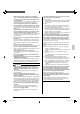
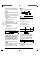
<Pattern 2>
When an obstruction on the air outlet side is lower than the
outdoor unit (There is no restriction in the height of obstruction
on the air inlet side.)
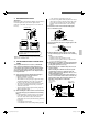
When the upward area is open •
When one outdoor unit is installed individually(1)
4 or more
20 or more
H
L
L>H
When two or more outdoor units are installed side (2)
by side
L
60 or more
H
A
The dimensional relationship between H, L and A is as
shown in the table below.
LA
0 < L ≤ 1/2H 10
1/2H < L ≤ H
12
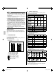
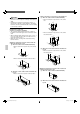
When an obstruction is present also in the upward area •
When one outdoor unit is installed individually(1)
L
40 or more
40 or more
20 or less
H
A
The dimensional relationship between H, L and A is as
shown in the table below.
LA
L ≤ H
0 < L ≤ 1/2H 4
1/2H < L ≤ H
8
H < L Install the frame to achieve “L
≤ H”.
NOTE
Close the area under the frame so that the outlet air does •
not bypass there.
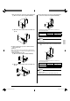
When only two outdoor units are installed side by (2)
side
60 or more
20 or less
H
L
A
40 or more
The dimensional relationship between H, L and A is as
shown in the table below.
LA
L ≤ H
0 < L ≤ 1/2H
10
1/2H < L ≤ H
12
H < L Install the frame to achieve “L
≤ H”.
NOTE
Close the area under the frame so that the outlet air does 1.
not bypass there.
Only two outdoor units can be installed side by side.2.
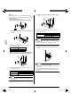
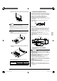
(D) When outdoor units are stacked
When an obstruction is present on the air outlet (1)
side
4
Z
40 or more
NOTE
Only two outdoor units can be stacked.1.
About 4 in. is required as the drain piping size for the upper 2.
outdoor unit.
Close the area Z (gap between the upper outdoor unit and 3.
the lower outdoor unit) so that the outlet air does not by-
pass there.
01_EN_3PA60114-14U.indd 701_EN_3PA60114-14U.indd 7 2/24/2009 5:23:06 PM2/24/2009 5:23:06 PM