INSTALLATION MANUAL SPLIT SYSTEM Air Conditioners English MODELS RZQ18PVJU RZQ24PVJU RZQ30PVJU Français Español Read these instructions carefully before installation. Keep this manual in a handy place for future reference. This manual should be left with the equipment owner. Lire soigneusement ces instructions avant l’installation. Conserver ce manuel à portée de main pour référence ultérieure. Ce manuel doit être donné au propriétaire de l’équipement.
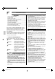
SPLIT SYSTEM Air Conditioners CONTENTS 1. 2. 3. 4. 5. 6. 7. 8. 9. 10. SAFETY CONSIDERATIONS ........................................... 1 INTRODUCTION ............................................................... 3 BEFORE INSTALLATION .................................................. 4 SELECTION OF INSTALLATION LOCATION ................... 4 CAUTIONS ON INSTALLATION ........................................ 8 REFRIGERANT PIPING WORK ....................................... 8 ELECTRIC WIRING WORK ........
• When wiring the power supply and connecting the remote controller wiring and transmission wiring, position the wires so that the terminal cover (panel) can be securely fastened. Improper positioning of the electric parts box lid may result in electric shocks, fire or the terminals overheating. • Before touching electrical parts, turn off the power. • Securely install the outside unit terminal cover (panel).
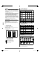
2-2 Technical specifications NOTE • Install the indoor and outdoor units, power supply wiring and transmission wiring at least 3.5ft. away from televisions or radios in order to prevent image interference or noise. (Depending on the radio waves, a distance of 3.5ft. may not be enough to eliminate the noise.) • Dismantling of the unit, treatment of the refrigerant, oil and eventual other parts, should be done in accordance with the relevant local and national regulations.
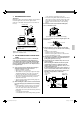
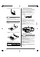
3. BEFORE INSTALLATION 〈Bringing-in〉 Bring in the outdoor unit slowly by holding the lugs provided on the left and right sides as shown in the figures below. (Take care so that hands and objects do not touch the fin on the rear.) Discharge grille • The operation is stopped by pressure rise. • If excessive strong wind continuously blows from the air outlet side of the outdoor unit, the fan may rotate in the reverse direction at high speed, and lead to damage.
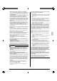
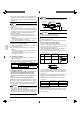
Installation place (unit: inch) 〈Cautions on continuous installation〉 • The connection piping outlet direction in the continuous installation shown in the figures below is frontward or downward. • When routing the piping rearward, secure space of 10 in. or more on the right side of the outdoor unit. (The unit of numeric values below is “inch”.) • Make some space for wiring with conduit and servicing between the units.
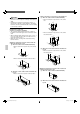
• When an obstruction is present also in the upward area (1) When one outdoor unit is installed individually • When an obstruction is present also in the upward area (1) When one outdoor unit is installed individually s r les s r les 40 or more 20 o L 40 or more 20 o 20 ore H ore 10 or m or m A (2) When two or more outdoor units are installed side by side The dimensional relationship between H, L and A is as shown in the table below.
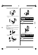
(2) When only two outdoor units are installed side by side ss 40 or more r le o 20 L L H H When an obstruction on the air outlet side is lower than the outdoor unit (There is no restriction in the height of obstruction on the air inlet side.
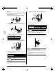
(2) When an obstruction is present on the air inlet side CAUTIONS ON INSTALLATION • Before installation, confirm the strength and levelness of the foundation so that vibrations and noise are not generated. • Fix the outdoor unit securely on a rigid base with foundation bolts as shown in the foundation drawing below. (Prepare 4 sets of commercially available M12-type or equivalent foundation bolts, nuts and washers.) • Use resin washers to prevent the paint from being scratched off and rusting.
must be 9mg/10ft. or less. 2. Use the following material specification for refrigerant pipping: • construction material: Phosphoric acid deoxidized seamless copper for refrigerant. • size: Determine the proper size referring to chapter “Example of connection”. 6-2 Protection of piping • Protect the pipings to prevent moisture and dusts from coming into the pipings. • Especially, pay attention when passing the pipings through a hole or connecting the end of piping to the outdoor.
6-4 Refrigerant piping work procedure The field piping can be connected in three directions. Front panel WARNING • Make sure to insulate the field piping up to the piping connection area inside the unit. If the piping is exposed, dew condensation and burn by contact may be caused.
NOTE Liquid piping length × 0.036 (ft.)×0.036 Record the additional amount to the label sticked on the back of front panel. • Charge the refrigerant to the liquid pipe in its liquid state. Since R410A is a mixed refrigerant, its composition changes if charged in a state of gas and normal system operation would no longer be assured. • Before filling, check whether the tank has a siphon attached or not. How to fill a tank with a siphon attached. Fill with the tank upright.
7. Service port ELECTRIC WIRING WORK DANGER Valve stem Silicon sealant Valve cap (Take care not to generate cavity.) Field piping connection part Opening direction • Do not ground units to water pipes, telephone wires or lightning rods because incomplete grounding could cause a severe shock hazard resulting in severe injury or death, and to gas pipes because a gas leak could result in an explosion which could lead to severe injury or death.
7-1 Connection example of whole system wiring Power Earth leakage circuit interrupter Branch switch Overcurrent breaker (fuse) 7-3 Power supply wiring connection procedure WARNING Outdoor unit • Never connect power supply wiring to the terminal block for remote controller wiring as this could damage the entire system. Install an earth leakage circuit interrupter. • It is obliged to install an earth leakage circuit interrupter to prevent electric shock and fire accident.
How to Insulation tube. • Use the insulation tube large to cover the power supply wiring. Use the insulation tube small to cover the transmission wiring. • Joint the insulation tube with the tape and cut off the tube sticking out of the outdoor unit. tape 7-4 Transmission wiring connection procedure • If an excessive force is applied while connecting a cable to the terminal block on the PC board, the PC board may be damaged.
DEMAND H7P ON H6P 01_EN_3PA60114-14U.indd 15 OFF L.N.O.P. 15 H5P • Make sure to perform the check operation after installation. (If the air conditioner is operated using the indoor remote controller without performing the check operation, the malfunction code “U3” is displayed in the indoor remote controller, and normal operation is disabled.) H4P 9-1 Power on and check operation SLAVE Cautions before turning on the power • Put the insulating cover securely onto the electric parts box.
• If the air conditioner is started within about 12 minutes after the power of the indoor/outdoor unit is turned on, the H2P indicator lights and the compressor does not run. Confirm that the LED status is as shown in the table in (2) in “9-1 Power on and check operation” before starting the air conditioner. • The air conditioner may require about 10 minutes maximum until it can start the compressor after start of operation.
When nothing is displayed in the remote controller • There might be a problem with the connection or transmission between the indoor unit and the remote controller. Check connections, and check for wire breakage. CAUTION • After finishing the test operation and before using the unit by customer, confirm that the outside panels and screws are attached securely to the units. 10.
3PA60114-14U EM08A096 00_CV_3PA60114-14U.