Service manual
Manuals
Brands
Daikin Manuals
Air Conditioner
RZQ140B7W1B
71
72
73
74
75
76
77
78
79
80
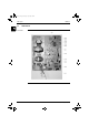
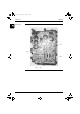
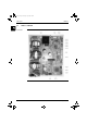
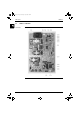
PCB Layout
ESIE05-03
1–52
Part 1 – System Outline
3
1
1
4
5
Inverter PC
B
The illus
tration below s
hows t
he PCB connecto
rs.
ESIE05-03.book
Page 52
Wednesday, April 6,
2005 4:09
PM
1
...
...
72
73
74
75
76
...
...
326