SiBE01 - 829 SPLIT Pair Wall Mounted Type G-Series [Applied Models] Non-Inverter Pair : Heat Pump
SiBE01-829 Non Inverter Pair G-Series zHeat Pump Indoor Unit FTYN25GXV1B FTYN35GXV1B FTY25GXV1 FTY35GXV1 Outdoor Unit RYN25GXV1B RYN35GXV1B Table of Contents RY25GXV1 RY35GXV1 i
SiBE01-829 1. Introduction .............................................................................................v 1.1 Safety Cautions ........................................................................................v 1.2 Used Icons .............................................................................................. ix Part 1 List of Function .................................................................. 1 1. Functions............................................................
SiBE01-829 Part 6 Service Diagnosis............................................................. 51 1. 2. 3. 4. Caution for Diagnosis............................................................................52 Problem Symptoms and Measures .......................................................53 Service Check Function ........................................................................54 Troubleshooting ....................................................................................55 4.
SiBE01-829 2. Wiring Diagrams..................................................................................113 2.1 Indoor Units ..........................................................................................113 2.2 Outdoor Units .......................................................................................113 Index ............................................................................................. i Drawings & Flow Charts ................................................
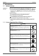
SiBE01-829 Introduction 1. Introduction 1.1 Safety Cautions Cautions and Warnings Be sure to read the following safety cautions before conducting repair work. The caution items are classified into “ Warning” and “ Caution”. The “ Warning” items are especially important since they can lead to death or serious injury if they are not followed closely. The “ Caution” items can also lead to serious accidents under some conditions if they are not followed.
Introduction SiBE01-829 Warning Be sure to wear a safety helmet, gloves, and a safety belt when working at a high place (more than 2m). Insufficient safety measures may cause a fall accident. In case of R410A refrigerant models, be sure to use pipes, flare nuts and tools for the exclusive use of the R410A refrigerant. The use of materials for R22 refrigerant models may cause a serious accident such as a damage of refrigerant cycle as well as an equipment failure.
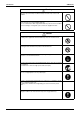
SiBE01-829 Introduction 1.1.2 Cautions Regarding Safety of Users Warning Be sure to use parts listed in the service parts list of the applicable model and appropriate tools to conduct repair work. Never attempt to modify the equipment. The use of inappropriate parts or tools may cause an electrical shock, excessive heat generation or fire. If the power cable and lead wires have scratches or deteriorated, be sure to replace them.
Introduction SiBE01-829 Warning Check to make sure that the power cable plug is not dirty or loose, then insert the plug into a power outlet securely. If the plug has dust or loose connection, it may cause an electrical shock or fire. Be sure to install the product correctly by using the provided standard For unitary type installation frame. only Incorrect use of the installation frame and improper installation may cause the equipment to fall, resulting in injury.
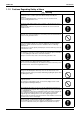
SiBE01-829 Introduction Caution Be sure to measure the insulation resistance after the repair, and make sure that the resistance is 1 MΩ or higher. Faulty insulation may cause an electrical shock. Be sure to check the drainage of the indoor unit after the repair. Faulty drainage may cause the water to enter the room and wet the furniture and floor. Do not tilt the unit when removing it. The water inside the unit may spill and wet the furniture and floor.
Introduction x SiBE01-829
SiBE01-829 Part 1 List of Function 1. Functions.................................................................................................
Functions SiBE01-829 Basic Function Functions Comfortable Airflow { Operation Limit for Cooling (°CDB) Photocatalytic Deodorizing Filter — Operation Limit for Heating (°CWB) –10 ~15 Air Purifying Filter with Photocatalytic Deodorizing Function — — Titanium Apatite Photocatalytic Air-Purifying Filter — Oval Scroll Compressor — Longlife Filter — Swing Compressor — Air Filter { Rotary Compressor { Wipe-clean Flat Panel { Reluctance DC Motor — Washable Grille — — Power-Airflow Fl
Category Basic Function Compressor Comfortable Airflow Functions Inverter (with Inverter Power Control) Lifestyle Convenience — Health & Clean Functions Operation Limit for Cooling (°CDB) 10 ~46 Air Purifying Filter { Operation Limit for Heating (°CWB) –10 ~24 Photocatalytic Deodorizing Filter — PAM Control — Air Purifying Filter with Photocatalytic Deodorizing Function — Oval Scroll Compressor — Swing Compressor — Titanium Apatite Photocatalytic Air-Purifying Filter — Rotary Com
Functions 4 SiBE01-829 List of Function
SiBE01-829 Part 2 Specifications 1. Specifications ..........................................................................................
Specifications SiBE01-829 1. Specifications 50Hz 230V Indoor Units Models Outdoor Units Capacity Rated (Min.~Max.) Running Current (Rated) Power Consumption Rated (Min.~Max.) Power Factor COP (Rated) Liquid Piping Connections Gas Drain Heat Insulation Max. Interunit Piping Length Max.
SiBE01-829 Specifications 50Hz 220V Indoor Units Models Outdoor Units Capacity Running Current Power Consumption Power Factor COP Liquid Piping Connections Gas Drain Heat Insulation Max. Interunit Piping Length Max.
Specifications 8 SiBE01-829 Specifications
SiBE01-829 Part 3 Printed Circuit Board Connector Wiring Diagram 1. Printed Circuit Board Connector Wiring Diagram..................................10 1.1 Indoor Unit..............................................................................................
Printed Circuit Board Connector Wiring Diagram SiBE01-829 1. Printed Circuit Board Connector Wiring Diagram 1.
SiBE01-829 Printed Circuit Board Connector Wiring Diagram Control PCB FU1 H1 V1 S2 H2 S1 V2 H3 S4 H4 S5 H5 NOT FIXED S7 S6 S33 S27 LED A J30 JC JA S32 (R4670) Signal Receiver PCB LED1 LED2 S26 RTH SW1 (R4671) Printed Circuit Board Connector Wiring Diagram 11
Printed Circuit Board Connector Wiring Diagram 12 SiBE01-829 Printed Circuit Board Connector Wiring Diagram
SiBE01-829 Part 4 Functions and Control 1. Functions...............................................................................................14 1.1 1.2 1.3 1.4 1.5 1.6 1.7 1.8 Power-Airflow Flap, Wide-Angle Louvers and Auto-Swing ....................14 Fan Speed Control for Indoor Units........................................................15 Thermostat Control.................................................................................16 Automatic Operation.....................................
Functions SiBE01-829 1. Functions 1.1 Power-Airflow Flap, Wide-Angle Louvers and AutoSwing Power-Airflow Flap The large flap send a large volume of air downwards to the floor. The flap provides an optimum control area in cooling, heating and dry mode. Heating Mode During heating mode, the large flap enables direct warm air straight downwards. The flap presses the warm air above the floor to reach the entire room. Cooling Mode During cooling mode, the flap retracts into the indoor unit.
SiBE01-829 1.2 Functions Fan Speed Control for Indoor Units Control Mode The airflow rate can be automatically controlled depending on the difference between the set temperature and the room temperature. This is done through phase control and Hall IC control. For more information about Hall IC, refer to troubleshooting for fan motor on page 59. Phase Steps Phase control and fan speed control contains 5 steps:LL, L, M, H, and HH.
Functions 1.3 SiBE01-829 Thermostat Control Thermostat control is based on the difference between the room temperature and the setpoint. Cooling Thermostat OFF: Room temperature – setpoint ≤ −1°C Thermostat ON : Room temperature – setpoint ≥ +1.5°C Room temperature – setpoint ON +1.5˚C –1˚C OFF (R8488) Heating Thermostat OFF: Room temperature – setpoint ≥ +3.5°C Thermostat ON : Room temperature – setpoint ≤ +1°C Room temperature – setpoint OFF +3.
SiBE01-829 1.4 Functions Automatic Operation Outline When the automatic mode is selected with the remote controller, the microcomputer determines the operation mode from cooling and heating according to the room temperature and the setpoint. The unit automatically switches the operation mode to cooling or heating to maintain the room temperature. Details of the Control Target temperature equals setpoint plus correction value (cooling:0°C, heating: –1.
Functions 1.5 SiBE01-829 Programme Dry Function Outline Programme dry function removes humidity while preventing the room temperature from lowering. Since the microcomputer controls airflow rate, the fan adjustment buttons are inoperable in this mode. Details of the Control During the first 12 minutes of the DRY mode run from: 1. After operation halt for 2 hours or more or 2.
SiBE01-829 Functions 4. If set temp. – room temp. > 3°C, then the operation is in Zone D. ZONE D ON Compressor 12 min. OFF L tap ON OFF 30 sec.
Functions 1.6 SiBE01-829 Sleep Operation When the Sleep Operation is set, the Sleep Operation circuit activates. The Sleep Operation circuit maintains the airflow setting made by users. The Sleep Operation Circuit When the unit is operating under cooling mode, the set temperature is increased by 0.5°C after the first half an hour, 1°C after the second half an hour and total of 2°C after the following 1 hour. This function will prevent excessive cooling during summer season.
SiBE01-829 1.7 Functions POWERFUL Operation Outline In order to exploit the cooling and heating capacity to full extent, operate the air conditioner by increasing the indoor fan rotating speed. Details of the Control When POWERFUL button is pushed, the fan speed and the target temperature will be converted to the following states for 20 minutes. Operation mode Cooling Heating Fan speed HH tap Target temperature Set temp. –2°C HH tap Set temp. +2°C Ex.) : POWERFUL operation in cooling mode.
Functions 1.8 SiBE01-829 Other Functions 1.8.1 Hot Start Function In order to prevent the cold draft that normally comes when heating operation starts, the temperature of the indoor heat exchanger is detected, and either the airflow is stopped or is made very weak thereby carrying out comfortable heating of the room. *The cold draft is also prevented using a similar control when the thermostat turns OFF. 1.8.
SiBE01-829 Function of Thermistor 2. Function of Thermistor A B Four way valve Compressor (R4733) A Outdoor Heat Exchanger Thermistor 1. The outdoor heat exchanger thermistor is used for high pressure control during cooling operation. B Indoor Heat Exchanger Thermistor 1. The indoor heat exchanger thermistor is used to prevent freezing. During the cooling operation, if the temperature drops abnormally, the operating frequency becomes lower, then the operation must be halted. 2.
Control Specification SiBE01-829 3. Control Specification 3.1 Four Way Valve Switching Outline Current is conducted during heating operation, and current is not conducted during cooling or defrosting. In order to eliminate the switching sound (as the four way valve coil switches from ON to OFF) when the heating is stopped, the delay switch of the four way valve is carried out after the operation stopped. Detail The four way valve is switched 150 sec. after the compressor stops. 3.
SiBE01-829 3.5 Control Specification Heating Peak-cut Control Outline During heating operation, heating peak-cut control is activated according to the temperature of the indoor heat exchanger to prevent abnormal high pressure. Detail Conditions for starting Temperature of the indoor heat exchanger > 68°C. While controlling The compressor halts. The outdoor fan switches ON/OFF according to the temperature of the indoor heat exchanger.
Control Specification 3.6 SiBE01-829 Defrost Control Outline In heating, defrosting is carried out by the cooling cycle (reverse cycle) to prevent the outdoor heat exchanger being frosted. The defrosting time or outdoor heat exchanger temperature must be more than its fixed value when finishing. Detail Time chart Heating Defrosting Heating 60sec. Compressor 230sec. ON OFF 50sec. Four way valve Outdoor unit fan Indoor unit fan 50sec.
SiBE01-829 Part 5 Operation Manual 1. System Configuration............................................................................28 2. Instructions ......................................................................................................29 2.1 2.2 2.3 2.4 2.5 2.6 2.7 2.8 2.9 2.10 2.11 2.12 Operation Manual Safety Precautions .................................................................................29 Names of Parts..................................................................
System Configuration SiBE01-829 1. System Configuration After the installation and test operation of the room air conditioner have been completed, it should be operated and handled as described below. Every user would like to know the correct method of operation of the room air conditioner, to check if it is capable of cooling (or heating) well, and to know a clever method of using it.
SiBE01-829 Instructions 2. Instructions Note: 2.1 This instruction is for FTYN models as representative. Safety Precautions READ BEFORE OPERATION Safety precautions • • • • Keep this manual where the operator can easily find them. Read this manual attentively before starting up the unit. For safety reason the operator must read the following cautions carefully. This manual classifies precautions into WARNING and CAUTION.
Instructions SiBE01-829 • Do not block air inlets nor outlets. Impaired air flow may result in insufficient performance or trouble. • Do not stand or sit on the outdoor unit. Do not place any object on the unit to avoid injury, do not remove the fan guard. • Do not place anything under the indoor or outdoor unit that must be kept away from moisture. In certain conditions, moisture in the air may condense and drip. • After a long use, check the unit stand and fittings for damage.
SiBE01-829 2.
Instructions SiBE01-829 Outdoor Unit 15 17 18 16 19 Indoor Unit 1. Air filter 2. Air purifying filter with bacteriostatic, virustatic functions: • These filters are attached to the inside of the air filters. 11. Indoor Unit ON/OFF switch: • Push this switch once to start operation. Push once again to stop it. • The operation mode refers to the following table. 3. Air inlet Mode 4. Front panel AUTO 5.
SiBE01-829 Instructions Remote Controller 1 2 2. Display: • It displays the current settings. (In this illustration, each section is shown with all its displays ON for the purpose of explanation.) 3 3. ON/OFF button: • Press this button once to start operation. • Press once again to stop it. P1 P2 ˚F ˚C AUTO AM ON PM OFF 4 14 13 12 10 6 5 MODE 7 8 SLEEP SET SET ON TIMER OFF TIMER CLR CLR 1. Signal transmitter: • It sends signals to the indoor unit. 9 4.
Instructions 2.3 SiBE01-829 Preparation Before Operation Preparation Before Operation To set the batteries P1 P2 ˚F ˚C 1. Slide the battery cover by pulling it according to the arrow direction. AUTO AM ON PM OFF 2. Insert new batteries making sure that the (+) and (–) of battery are installed correctly. 3. Reattach the cover by sliding it back into position.
SiBE01-829 Instructions Preparation Before Operation To operate the remote controller • To use the remote controller, aim the transmitter at the indoor unit. If there is anything to block signals between the unit and the remote controller, such as a curtain, the unit will not operate. • Do not drop the remote controller. Do not get it wet. • The maximum distance for communication is about 7m. Receiver To fix the remote controller holder on the wall 1.
Instructions SiBE01-829 To set the clock 1. Hold down “ 2 seconds. ” or “ ” button for P1 P2 ûF ˚C AUTO 2. Press “ ” button to increase the clock time. AM ON PM OFF 3. Press “ ” button to decrease the clock time. 4. Leave the remote controller for 4 seconds without pressing any button. 1, 2 1, 3 MODE SLEEP SET SET ON TIMER OFF TIMER CLR CLR NOTE Tips for saving energy • Be careful not to cool (heat) the room too much.
SiBE01-829 2.4 Instructions AUTO • DRY • COOL • HEAT • FAN Operation OPERATION AUTO · DRY · COOL · HEAT · FAN Operation The air conditioner operates with the operation mode of your choice. From the next time on, the air conditioner will operate with the same operation mode. P1 P2 ûF To start operation ˚C AUTO 1. Press “MODE selector button” and select a operation mode. AM ON PM OFF 2, 3 • Each pressing of the button advances the mode setting in sequence.
Instructions SiBE01-829 To change the airflow rate setting 5. Press “FAN setting button”. DRY mode AUTO or COOL or HEAT or FAN mode 3 levels of airflow rate setting from “ “ ” are available. ” to “ ” plus The airflow rate setting is not variable. NOTE Note on HEAT operation • Since this air conditioner heats the room by taking heat from outdoor air to indoors, the heating capacity becomes smaller in lower outdoor temperatures.
SiBE01-829 2.5 Instructions Adjusting the Airflow Direction Adjusting the Airflow Direction You can adjust the airflow direction to increase your comfort. To adjust the horizontal blades (flaps) P1 P2 ûF ˚C AUTO 1. Press “SWING button”. • “ AM ON PM OFF ” is displayed on the LCD and the flaps will begin to swing. 2. When the flaps have reached the desired position, press “SWING button” once more. MODE • The flap will stop moving. 1, 2 SLEEP • “ ” disappears from the LCD.
Instructions 2.6 SiBE01-829 POWERFUL Operation POWERFUL Operation POWERFUL operation quickly maximizes the cooling (heating) effect in any operation mode. You can get the maximum capacity. P1 P2 To start POWERFUL operation ûF ˚C AUTO AM ON PM OFF 1. Press “POWERFUL button”. • POWERFUL operation ends in 20minutes. Then the system automatically operates again with the previous settings which were used before POWERFUL operation. 1, 2 MODE • “ ” is displayed on the LCD.
SiBE01-829 2.7 Instructions QUIET Operation QUIET Operation QUIET operation lowers the noise level of the indoor unit by changing the airflow rate minimum. Use this when making the noise quieter. P1 P2 To start QUIET operation ûF ûC AUTO 1. Press “QUIET button”. • “ AM ON PM OFF ” displayed on the LCD. To cancel QUIET operation 2. Press “QUIET button” again. MODE • “ ” disappears from the LCD.
Instructions 2.8 SiBE01-829 TIMER Operation TIMER Operation Timer functions are useful for automatically switching the air conditioner on or off at night or in the morning. You can also use OFF TIMER and ON TIMER in combination. P1 P2 To use OFF TIMER operation ûF ˚C • Check that the clock is correct. If not, set the clock to the present time. (page 9.) AUTO AM ON PM OFF 1. Press “OFF TIMER SET button” until the indicated time reaches the point you like.
SiBE01-829 2.9 Instructions PERSONALIZE Operation PERSONALIZE Operation PERSONALIZE operation is the function which allows you to record your preferred settings. You can set your preferred setting one time by using this function. P1 P2 ûF ˚C To set PERSONALIZE operation AUTO AM ON PM OFF 1. Hold down “PERSONALIZED button” until “P1” blinks. • Press again to cycle between “P1” and “P2”. Choose P1 or P2. MODE 2. Set your preferred setting. SLEEP 3.
Instructions SiBE01-829 2.10 SLEEP Operation SLEEP Operation When set SLEEP operation, the air conditioner automatically adjusts the temperature setting. P1 P2 To set SLEEP operation ûF ûC AUTO 1. Press “SLEEP button”. • AM ON PM OFF is displayed. To cancel SLEEP operation 2. Press “SLEEP button” again. • disappears.
SiBE01-829 Instructions 2.11 Care and Cleaning CARE Care and Cleaning CAUTION Before cleaning, be sure to stop the operation and turn the breaker OFF. Units Indoor unit, Outdoor unit and Remote controller 1. Wipe them with dry soft cloth. Front panel 1. Open the front panel. Recess on main unit • Hold the panel at the recesses on the main unit (2 recesses on right and left sides) and lift it until it stops. 2. Remove the front panel.
Instructions SiBE01-829 Filters 1. Open the front panel. (page 18.) Recess on main unit • Hold the panel at the recesses on the main unit (2 recesses on right and left sides) and lift it until it stops. 2. Pull out the air filters. • Push a little upwards the tab at the center of each air filter, then pull it down. 3. Take off the Air purifying filter with bacteriostatic, virustatic functions. • Hold the recessed parts of the frame and unhook the four claws. 4. Clean or replace each filter.
SiBE01-829 Instructions [ Maintenance ] 1. Remove dust with a vacuum cleaner and wash lightly with water. 2. If it is very dirty, soak it for 10 to 15 minutes in water mixed with a neutral cleaning agent. 3. Do not remove filter from frame when washing with water. 4. After washing, shake off remaining water and dry in the shade. 5. When shaking off remaining water, do not wring the filter. [ Replacement ] 1. Remove the tabs on the filter frame and replace with a new filter.
Instructions SiBE01-829 2.12 Troubleshooting TROUBLE SHOOTING Trouble Shooting These cases are not troubles. The following cases are not air conditioner troubles but have some reasons. You may just continue using it. Case Explanation Operation does not start soon. • This is to protect the air conditioner. You should wait for about 3 minutes. • When ON/OFF button was pressed soon after operation was stopped. • When the mode was reselected.
SiBE01-829 Instructions Check again. Please check again before calling a repair person. Case The air conditioner does not operate. (OPERATION lamp is off.) Check • Hasn’t a breaker turned OFF or a fuse blown? • Isn’t it a power failure? • Are batteries set in the remote controller? • Is the timer setting correct? Cooling (Heating) effect is poor.
Instructions SiBE01-829 Call the service shop immediately. WARNING When an abnormality (such as a burning smell) occurs, stop operation and turn the breaker OFF. Continued operation in an abnormal condition may result in troubles, electric shocks or fire. Consult the service shop where you bought the air conditioner. Do not attempt to repair or modify the air conditioner by yourself. Incorrect work may result in electric shocks or fire. Consult the service shop where you bought the air conditioner.
SiBE01-829 Part 6 Service Diagnosis 1. 2. 3. 4. Caution for Diagnosis............................................................................52 Problem Symptoms and Measures .......................................................53 Service Check Function ........................................................................54 Troubleshooting ....................................................................................55 4.1 Error Codes and Description .........................................
Caution for Diagnosis SiBE01-829 1. Caution for Diagnosis The operation lamp flashes when any of the following errors is detected. 1. When a protection device of the indoor or outdoor unit is activated or when the thermistor malfunctions, disabling equipment operation. 2. When a signal transmission error occurs between the indoor and outdoor units. In either case, conduct the diagnostic procedure described in the following pages.
SiBE01-829 Problem Symptoms and Measures 2. Problem Symptoms and Measures Problem Check None of the units operates. Check the power supply. Check the type of the indoor units. Check the outdoor air temperature. Diagnosis with remote controller indication Check the remote controller addresses. Operation sometimes stops. Check the power supply. Check the outdoor air temperature. Diagnosis with remote controller indication Equipment operates but does not cool, or does not heat.
Service Check Function SiBE01-829 3. Service Check Function The temperature display sections on the main unit indicate corresponding codes. Check Method 1. When the ON timer or OFF timer cancel button is held down for 5 seconds, a “00” indication flashes on the temperature display section. P1 P2 ßF AUTO ßC AM ON PM OFF MODE SLEEP SET SET ON TIMER OFF TIMER CLR CLR TIMER CANCEL button (R8500) 2. Press either ON timer or OFF timer cancel button repeatedly until a long beep is produced.
SiBE01-829 Troubleshooting 4. Troubleshooting 4.
Troubleshooting 4.2 SiBE01-829 Indoor Unit PCB Abnormality A1 Remote Controller Display Method of Malfunction Detection Evaluation of zero-cross detection of power supply by indoor unit. Malfunction Decision Conditions When there is no zero-cross detection in approximately 1.25 continuous seconds.
SiBE01-829 4.3 Troubleshooting Freeze-up Protection Control, High Pressure Control or Indoor Heat Exchanger Thermistor Abnormality Remote Controller Display A5 Method of Malfunction Detection High pressure control Malfunction Decision Conditions High pressure control Supposed Causes Service Diagnosis During heating operations, the temperature detected by the indoor heat exchanger thermistor is used for the high pressure control (stop, outdoor fan stop, etc.
Troubleshooting SiBE01-829 Troubleshooting Caution Check No.06 Refer to P.67 Be sure to turn off power switch before connect or disconnect connector, or parts damage may be occurred. Check the stop valve. Is it opened? NO Open the stop valve. YES Check the air passage. Is there any short-circuit? YES Provide sufficient air passage. NO Check the intake air filter. Is it very dirty? YES Clean the air filter. NO Check the dust accumulation on the indoor unit heat exchanger.
SiBE01-829 4.4 Troubleshooting Fan Motor or Related Abnormality (AC motor) Remote Controller Display A6 Method of Malfunction Detection The rotation speed detected by the Hall IC during fan motor operation is used to determine abnormal fan motor operation. Malfunction Decision Conditions When the detected rotation speed is less than 50% of each tap under maximum fan motor rotation demand. Supposed Causes NOT FIXED Operation halt due to short circuit inside the fan motor winding.
Troubleshooting 4.5 SiBE01-829 Thermistor or Related Abnormality 4.5.1 Heat Exchanger Thermistor Remote Controller Display C4, J6 Method of Malfunction Detection The temperatures detected by the indoor and outdoor heat exchanger thermistors are used to determine thermistor errors. Malfunction Decision Conditions When the indoor and outdoor heat exchanger thermistor input is 0.04 V or less during compressor operation∗.
SiBE01-829 Troubleshooting 4.5.2 Room Temperature Thermistor Remote Controller Display C9 Method of Malfunction Detection The temperatures detected by the room temperature thermistor is used to determine thermistor error. Malfunction Decision Conditions When the room temperature thermistor input is more than 4.96 V or more, or 0.04 V or less during compressor operation∗. ∗ (Reference) Room temperature thermistor: 30Ω or less, or 490kΩ or more.
Troubleshooting 4.6 SiBE01-829 High Pressure Control in Cooling or Outdoor Heat Exchanger Thermistor Abnormality Remote Controller Display F6 Method of Malfunction Detection High-pressure control (stop) is activated in the cooling mode if the temperature being sensed by the heat exchanger thermistor exceeds the limit. The temperature detected by the outdoor heat exchanger thermistor is used to determine the abnormal thermistor.
SiBE01-829 Troubleshooting Troubleshooting Caution Check No.06 Refer to P.67 Check No.07 Refer to P.68 Be sure to turn off power switch before connect or disconnect connector, or parts damage may be occurred. Check the stop valve. Is it opened? NO Open the stop valve. YES Check No.09 Refer to P.69 Check the installation space. Check No. 07 Check the installation condition. Abnormal Normal Check No. 09 Check the outdoor fan. Abnormal Normal Change the air outlet grille position.
Troubleshooting 4.7 SiBE01-829 Hardware Error (Tact Switch Pin Short) Remote Controller Display UA Method of Malfunction Detection The supply power is detected for its requirement (different from pair type and multi type) by the indoor / outdoor transmission signal. Malfunction Decision Conditions The pair type and multi type are interconnected.
SiBE01-829 4.8 Troubleshooting Insufficient Gas Remote Controller Display U0 Method of Malfunction Detection A gas shortage is detected by checking the indoor unit heat exchanger temperature. Malfunction Decision Conditions When the compressor operates for 30 min. with the indoor heat exchanger temperature is and then, check for 5 more min. before determining insufficient gas and system down.
Troubleshooting SiBE01-829 Troubleshooting Check No.06 Refer to P.67 Caution Be sure to turn off power switch before connect or disconnect connector, or parts damage may be occurred. Is thermistor disconnected? YES Replace in position. * Indoor heat exchanger thermistor NO Stop valve closed? YES Open the stop valve. NO Check for gas leakage. Oil oozing at relay pipe connections? YES Repair the pipe flare or replace the square union.
SiBE01-829 Check 5. Check 5.1 Thermistor Resistance Check Check No.06 Remove the connectors of the thermistors on the PCB, and measure the resistance of each thermistor using tester. The relationship between normal temperature and resistance is shown in the graph and the table below. Temperature (°C) R25°C=10kΩ B=3450 Thermistor (kΩ) –20 –15 72.7 56.6 –10 –5 44.5 35.2 0 5 28.0 22.5 10 15 18.2 14.8 20 12.1 25 30 10.0 8.3 35 40 6.9 5.8 45 50 4.9 4.
Check 5.2 SiBE01-829 Installation Condition Check Check No.07 Installation condition check Check the allowable dimensions of the air suction and discharge area. Abnormal Change the position of the air discharge grille or the installation location. Normal Does the discharged air from other outdoor unit cause an increase of the suction air temperature? YES Change the position of the air discharge grille or the installation location.
SiBE01-829 5.3 Check Outdoor Unit Fan System Check Check No.09 Check the outdoor fan system. Does the outdoor fan rotate? NO YES Does the outdoor unit fan start just after the power is turned on? YES Abnormal Check the fan motor lead wire Repair. connector for secure connection. Normal NO Are the resistance at connector leads ∞? 1. red - black, 2. white - black YES Replace the fan motor. NO Continuity Check the fan Replace the fan motor. capacitor for continuity.
Check 70 SiBE01-829 Service Diagnosis
SiBE01-829 Part 7 Removal Procedure NOT FIXED 1. Indoor Unit.............................................................................................72 1.1 1.2 1.3 1.4 1.5 1.6 1.7 Removal of Air Filter...............................................................................72 Removal of Front Grille ..........................................................................75 Removal of Horizontal Blades / Vertical Blades .....................................
SiBE01-829 Part 8 Others 1. Others .................................................................................................106 1.1 Trial Operation and Testing..................................................................106 1.2 Pump Down Operation .........................................................................106 1.3 Jumper Settings ...................................................................................
Others SiBE01-829 1. Others 1.1 Trial Operation and Testing 1. Measure the supply voltage and make sure that it falls in the specified range. 2. Trial operation should be carried out in either cooling or heating mode. In cooling mode, select the lowest programmable temperature; in heating mode, select the highest programmable temperature. Trial operation may be disabled in either mode depending on the room temperature.
SiBE01-829 1.3 Others Jumper Settings 1.3.1 When Two Units are Installed in One Room How to set the different addresses. When two indoor units are installed in one room, the two wireless remote controllers can be set for different addresses. PCB in the indoor unit Remove the front panel. Remove the electrical parts box (1-screw). Slide the metallic cover to remove it. (4-claws on the electrical parts box.) Cut the jumper JA on PCB. NOT FIXED Wireless remote controller Cut the jumper J4.
Others 108 SiBE01-829 Others
SiBE01-829 Part 9 Appendix 1. Piping Diagrams..................................................................................110 1.1 Indoor Units ..........................................................................................110 1.2 Outdoor Units .......................................................................................111 2. Wiring Diagrams..................................................................................113 2.1 Indoor Units ......................................
Piping Diagrams SiBE01-829 1. Piping Diagrams 1.1 Indoor Units FTYN25GXV1B, FTY25GXV1 FTYN35GXV1B, FTY35GXV1 INDOOR UNIT INDOOR UNIT 7.0CuT HEAT EXCHANGER 7.0CuT FIELD PIPING (6.4CuT) 4.8CuT THERMISTOR ON HEAT EXCH. 7.0CuT 7.0CuT 7.0CuT 4.8CuT 7.0CuT CROSS FLOW FAN FIELD PIPING (6.4CuT) M FAN MOTOR FIELD PIPING (9.5CuT) THERMISTOR ON HEAT EXCH. 7.0CuT 7.0CuT CROSS FLOW FAN M FAN MOTOR FIELD PIPING (12.7CuT) 9.
SiBE01-829 1.2 Piping Diagrams Outdoor Units RYN25GXV1B OUTDOOR UNIT 9.5CuT 7.0CuT HEAT EXCHANGER 7.0CuT HEAT EXCHANGER THERMISTOR 6.4CuT 6.4CuT 6.4CuT 6.4CuT M PROPELLER FAN 9.5CuT CHECK VALVE 6.4CuT CAPILLARY TUBE 1 CAPILLARY TUBE 2 MUFFLER WITH FILTER 6.4CuT 9.5CuT FIELD PIPING LIQUID STOP (6.4CuT) VALVE 9.5CuT MUFFLER 7.9CuT 7.9CuT FOUR WAY VALVE ON:HEATING STRAINER 7.0CuT 9.5CuT 9.5CuT FIELD PIPING GAS STOP (9.
Piping Diagrams SiBE01-829 RY25GXV1 OUTDOOR UNIT 9.5CuT 7.0CuT HEAT EXCHANGER 7.0CuT HEAT EXCHANGER THERMISTOR 6.4CuT 6.4CuT 6.4CuT 6.4CuT M PROPELLER FAN 9.5CuT CHECK VALVE 6.4CuT CAPILLARY TUBE 1 CAPILLARY TUBE 2 MUFFLER WITH FILTER 6.4CuT 9.5CuT FOUR WAY VALVE ON:HEATING LIQUID STOP VALVE 9.5CuT MUFFLER 7.9CuT 7.9CuT STRAINER 7.0CuT FIELD PIPING (6.4CuT) 9.5CuT FIELD PIPING GAS STOP (9.
SiBE01-829 Wiring Diagrams 2. Wiring Diagrams 2.1 Indoor Units FTYN25GXV1B, FTYN35GXV1B, FTY25GXV1, FTY35GXV1 2.
Wiring Diagrams 114 SiBE01-829 Appendix
SiBE01-829 Index Numerics C9 ................................................................... 68 F6 .................................................................... 69 J6 .................................................................... 71 00 ...........................................................................63 3-minutes standby ............................................27, 29 A A1 ...........................................................................64 A5 ......................
SiBE01-829 left side plate ................................................101, 102 liquid compression protection function ...................30 liquid piping ............................................................92 M mold proof air filter .................................................27 N names of parts .......................................................37 night set mode ........................................................25 O ON/OFF button on indoor unit ..............................
SiBE01-829 Drawings & Flow Charts A D RN35DAV3B ................................................. 117 RN35DV3B ................................................... 117 RYN25DAV3B .............................................. 117 RYN25DV3B ................................................. 117 RYN35DAV3B .............................................. 117 RYN35DV3B ................................................. 117 POWERFUL operation .......................................... 26 programme dry function ..
SiBE01-829 iv Drawings & Flow Charts
Specifications, designs and other content appearing in this brochure are current as of May 2008 but subject to change without notice.