
Installation manual


RXYSQ4~6M7V3B
VRVII-S system air conditioner
4PW17806-1C
Installation manual
13
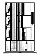
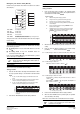
Field line connection: Control wiring and cool/heat selection
See figure 10.
Sequential start
Make the outdoor unit cable connections shown below.
The outdoor unit PC board (A1P) is factory set at "Sequential start
available".
Setting the cool/heat operation (heat pump unit only)
1 Performing cool/heat setting with the remote controller
connected to the indoor unit.
Keep the cool/heat selector switch (DS1) on the outdoor unit PC
board at the factory setting position IN/D UNIT. (See figure 11).
2 Performing cool/heat setting with the cool/heat selector.
Connect the cool/heat selector remote controller (optional) to the
A/B/C terminals and set the cool/heat selector switch (DS1) on
the outdoor unit PC board (A1P) to OUT/D UNIT. (See
figure 12).
■ The wiring from the indoor units must be connected to the F1/F2
(In-Out) terminals on the PC board in the outdoor unit.
■ After installing the interconnecting wires inside the unit, wrap
them along with the on-site refrigerant pipes using finishing
tape, as shown in figure 14.
For the above wiring, always use vinyl cords with 0.75 to 1.25 mm
2
sheath or cables (2 core wires). (3 core wire cables are allowable for
the cooler/heater changeover remote controller only.)
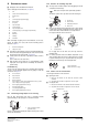
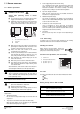
Precautions when laying power wiring
Use round pressure terminals for connections to the power
terminal block.
When none are available, follow the instructions below.
■ Do not connect wiring of different thicknesses to the
power terminal block. (Slack in the power wiring may
cause abnormal heat.)
■ When connecting wiring which is the same thickness,
do as shown in the figure below.
■ For wiring, use the designated power wire and
connect firmly, then secure to prevent outside
pressure being exerted on the terminal board.
■ Use an appropriate screwdriver for tightening the
terminal screws. A screwdriver with a small head will
strip the head and make proper tightening impossible.
■ Over-tightening the terminal screws may break them.
■ See the table below for tightening torque for the
terminal screws.
If an excessive force is applied while connecting a cable to
the terminal block on the PC board, the PC board may be
damaged.
1 Cool/heat selector (not required for cooling only units)
2 Outdoor unit PC board (A1P)
3 Take care of the polarity (not required for cooling only units)
4 Use the conductor of sheathed wire (2 wire) (no polarity)
5 Ter minal board (field supply)
12
1 Round pressure terminal
2 Power wire
Tightening torque (N•m)
M5 (Power terminal block/ground wire) 2.39~2.92
M4 (Shielded ground) 1.18~1.44
M3.5 (Control wiring block) 0.79~0.97
1 Remote controller
1 Cool/heat selector
For low-noise operation, it is necessary to get the optional
'External control adaptor for outdoor unit' (DTA104A61/62).
For details, see the installation manual attached to the
adaptor.
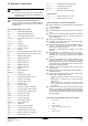
■ Be sure to follow the limits below. If the unit-to-unit
cables are beyond these limits, it may result in
malfunction of transmission.
Maximum wiring length: 1000 m
Total wiring length: 2000 m
Maximum No. of branches: 9
■ Up to 9 branches are possible for unit-to unit cabling.
No branching is allowed after branching. (See
figure 13).
■ Never connect the power supply to unit-to-unit cabling
terminal block. Otherwise the entire system may
break down.
1 Liquid pipe
2 Gas pipe
3 Interconnecting wiring
4 Insulator
5 Finishing tape
1 Branch
2 Subbranching