INSTALLATION MANUAL System air conditioner RXYSQ4M7V3B RXYSQ5M7V3B RXYSQ6M7V3B
3 B A 3 1 2 3 2 6 1 5 ≥1000 ≥1 0 00 ≥1 00 0 ≥1500 4 2 2 00 ≥15 00 ≥15 ≥1500 1 1 C (mm) 1 3 1 2 3 B 2 C 3 4 ≥100 ≥100 ≥100 ≥100 ≤500 ≥1000 ≥100 ≥150 B2 ≥500 ≤500 D2 E C L2 ≥500 L2>H ≥100 ≥500 L2H H B1 A ≤500 ≥1000 ≥150 ≥150 H
1 8 11 9 12 2 2 O U T TO IN/D UNIT F1 F2 ON DS1 OFF 1 I N 11 A1P 3 4 13 3 230 V 10 8 F1 F2 4 L 1 2 F1 F2 F1 F2 1 N 16 V 11 12 1 9 2 O U T 3 ON 230 V 16 V 16 V 4 16 V 1 I N 4 5 2 3 4 4 1 ABC 5 DS1 OFF ABC 12 5 13 8 2 A1 P 10 F1 F2 F1 F2 A B A1P TO IN/D UNIT TO OUT/D UNIT ABC C 1 3 C/H SELECTOR 2 1 7 1 6 5 4 2 A 3 2 2 3 3 F1 F2 } F1 F2 F1 F2 F1 F2 F1 F2 13 C } } 14 B 2 1 4 5 2 4 3 14 4 F1 F2 F1 F2 F1 F2 15 F1 F2 F1 F2
08 Nota * 07 ™ËÌ›ˆÛË * 06 Nota * 05 Nota * 04 Bemerk * 03 Remarque * 02 Hinweis * 01 Note * 10 under iagttagelse af bestemmelserne i: 11 enligt villkoren i: 12 gitt i henhold til bestemmelsene i: 13 noudattaen määräyksiä: 14 za dodržení ustanovení předpisu: 15 prema odredbama: 16 követi a(z): 17 zgodnie z postanowieniami Dyrektyw: 18 în urma prevederilor: 19 ob upoštevanju določb: 20 vastavalt nõuetele: 21 следвайки клаузите на: 22 laikantis nuostatų, pateikiamų: 23 ievērojot prasības, kas noteikt
RXYSQ4M7V3B RXYSQ5M7V3B RXYSQ6M7V3B CONTENTS VRVII-S system air conditioner Page 1. Safety considerations................................................................. 1 2. Introduction ................................................................................ 2 2.1. 2.2. 2.3. 2.4. Combination..................................................................................... 2 Standard supplied accessories........................................................ 2 Optional accessories .......
CAUTION ■ Ground the air conditioner. Grounding resistance should be according to national regulations Do not connect the earth wire to gas or water pipes, lightning conductor or telephone earth wire. Incomplete grounding may cause electric shocks. 2. INTRODUCTION 2.1. The indoor units can be installed in the following range. ■ Always use appropriate indoor units compatible with R-410A. To learn which models of indoor units are compatible with R-410A, refer to the product catalogs.
3. BEFORE INSTALLATION Since design pressure is 3.8 MPa or 38 bar, pipes of larger wall thickness may be required. Refer to paragraph "7.1. Selection of piping material" on page 5. 3.1. ■ ■ Since R-410A is a mixed refrigerant, the required additional refrigerant must be charged in its liquid state. (If the refrigerant is in state of gas, its composition changes and the system will not work properly). ■ The connected indoor units must be indoor units designed exclusively for R-410A.
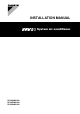
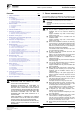
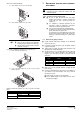
4 5 6 If the water drainage of the unit is not easy, please build up the unit on a foundation of concrete blocks, etc. (the height of the foundation should be maximum 150 mm). If you install the unit on a frame, please install a waterproof plate within 150 mm of the underside of the unit in order to prevent the invasion of water from the lower direction. When installing the unit in a place frequently exposed to snow, pay special attention to the following: - 7 5.1.
7. (B) In case of stacked installation 1. REFRIGERANT PIPE SIZE AND ALLOWABLE PIPE LENGTH In case obstacles exist in front of the outlet side. All field piping must be installed by a licensed refrigeration technician and must comply with relevant local and national regulations. 100 A To persons in charge of piping work: ■ Be sure to open the shut-off valve after piping installing and vacuming is complete. (Running the system with the valve closed may break the compressor.
8. ■ PRECAUTIONS ON REFRIGERANT PIPING Do not allow anything other than the designated refrigerant to get mixed into the freezing cycle, such as air, etc. If any refrigerant gas leaks while working on the unit, ventilate the room thoroughly right away. ■ 8.2. Cautions for flare connection ■ See the following table for flare part machining dimensions.
9. ■ REFRIGERANT 9.2. PIPING Field pipes can be installed in four directions. ■ Cautions for handling stop valve The stop valves for indoor-outdoor connecting piping are closed at shipment from the factory. Figure - Field pipes in four directions (See figure 5) Make sure to keep the valve open during operation.
9.4. Cautions for handling the valve cover ■ The valve cover is sealed where indicated by the arrow. Take care not to damage it. ■ After operating the valve, be sure to tighten the valve cover properly. Tightening torque ■ Liquid pipe 13.5~16.5 N•m Gas pipe 22.5~27.5 N•m Check for refrigerant leakage after tightening the cap. 9.5. Cautions for handling service port After the work, tighten the valve cover in place. Tightening torque: 11.5~13.9 N•m 9.6.
RXYSQ4~6M7V3B VRVII-S system air conditioner 4PW17806-1C Installation manual 9 i 2 c j C 3 d k D 4 e l E 5 f m F 6 g n G 7 H2 Difference in height Actual pipe length First refrigerant branch kit Indoor unit 3 3 How to calculate the additional refrigerant to be charged Additional refrigerant to be charged R (kg) R should be rounded off in units of 0.
9.7. Leak test and vacuum drying The units were checked for leaks by the manufacturer. To avoid compressor breakdown. Do not charge the refrigerant more than the specified amount. ■ This outdoor unit is factory charged with refrigerant and depending on pipe sizes and pipe lengths some systems require additional charging of refrigerant. See "How to calculate the additional refrigerant to be charged" on page 9.
10. ELECTRICAL WIRING WORK Y2S ........................ Solenoid valve (receiver gas purge) Y3S ........................ Solenoid valve (4 way valve) Z1C~Z3C ............... Noise filter (ferrity core) ■ All wiring must be performed by an authorized electrician. Z1F......................... Noise filter (with surge absorber) ■ All components procured on the site and all electric construction should comply with the applicable local and national codes. Cool/heat selector S1S ........................
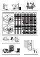
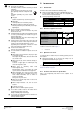
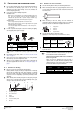
10.4. Connecting power wire and transmission wires ■ Let the power wire (including ground wire) go through the power outlet port on either the front, side or back of the outdoor unit. ■ Let the transmission wires go through the cable outlet port, pipe outlet port or knock out hole on either the front, side or back of the outdoor unit. (See figure 9).
Setting the cool/heat operation (heat pump unit only) Precautions when laying power wiring Use round pressure terminals for connections to the power terminal block. 1 Performing cool/heat setting with the remote controller connected to the indoor unit. Keep the cool/heat selector switch (DS1) on the outdoor unit PC board at the factory setting position IN/D UNIT. (See figure 11). When none are available, follow the instructions below.
11. BEFORE 3 OPERATION Power supply wiring and transmission wiring Use a designated power supply and transmission wiring and make sure that it has been carried out according to the instructions described in this manual, according to the wiring diagrams and according to local and national regulations. 11.1.
Setting the push button switch (BS1~5) Setting mode 2 Function of the push button switch which is located on the outdoor unit PCB (A1P): The H1P led is on. Setting procedure DEMAND H7P L. N. O. P H6P BS5 SLAVE H5P BS4 MASTER H4P IND H3P C/H SELECTOR 1 BS3 BS2 BS1 TEST: HWL: H2P MODE RESET Push the BS2 SET button according to the required function (A~F).
Performing the test operation Confirmation of the set mode The following items can be confirmed by setting mode 1 (H1P led is off) Check the led indication in the field marked 1 . Indication of the present operation state - normal - abnormal - under preparation or under test operation H1P 2 H2P H3P H4P H5P H6P 1 To protect the compressor, make sure to turn on the power supply 6 hours before starting operation. 2 Set to setting mode 1 (H1P led is off) (refer to "Setting mode 1" on page 15).
Error codes on the remote controller: Installation error In case of wireless remote controllers Malfunction code The stop valve of an outdoor unit is left closed. Refrigerant overcharge Open the stop valve on both the gas and liquid side. E3 Recalculate the required amount of refrigerant from the piping length and correct the refrigerant charge level by recovering any excessive refrigerant with a refrigerant recovery machine. The stop valve of an outdoor unit is left closed.
Refrigerant recovery operation method by a refrigerant reclaimer. 13.3. Procedure for checking maximum concentration 1 Check the maximum concentration level in accordance with steps 1 to 4 below and take whatever action is necessary to comply. When the unit is at standstill and in setting mode 2, set the required function B (refrigerant recovery operation/vacuuming operation) to ON (ON). - The indoor unit and the outdoor unit expansion valves will fully open and some solenoid valves will open.
NOTES
Zandvoordestraat 300, B-8400 Oostende, Belgium 4PW17806-1C