Commissioning Manual intelligent Touch Manager Model DCM601A51 MONITOR LAN SW FRONT BACK SERVICE LAN ON SLAVE OFF MASTER CPU ALIVE LAN LINK DⅢ MONITOR DⅢ MASTER BACKUP RESET
Contents System Overview.............................................................................4 1. About the iTM (intelligent Touch Manager).......................................................4 1-1 System Configuration.......................................................................................................... 4 2. Engineering.........................................................................................................5 2-1 Engineering Workflow.............................
4-8 Upgrade............................................................................................................................. 55 4-9 Backup............................................................................................................................... 56 4-10 Installation....................................................................................................................... 58 4-11 Contact Info.......................................................................
•• Logging into Service Mode via Web Remote Management......................................... 108 iTM integrator Explanation........................................................109 7. iTM integrator..................................................................................................109 7-1 Basic Setup..................................................................................................................... 109 7-2 iTM integrator Service Settings..................................
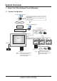
System Overview 1. About the iTM (intelligent Touch Manager) 1-1 System Configuration Web Remote Management Web Remote Management possible from networkconnected PC Simultaneous login of max. 4 managers and 16 users supported. Intranet/Internet Web Remote Management ROUTER Up to 64 groups HUB/SWITCH/ROUTER/....
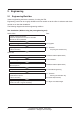
2. Engineering 2-1 Engineering Workflow Various engineering works are necessary for using the iTM. Engineering works can be roughly divided into those carried out at the office in advance and those carried out on site after installation. The following diagram shows the engineering workflow. New installation (Without using the pre-engineering tool) At the office See: Prepare various information. Check the equipment to connect to DIII-NET. Allocate the Group Address. Acquire the upgrade data.
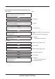
New installation (By using the pre-engineering tool) At the office See: Prepare various information. Check the equipment to connect to DIII-NET. Allocate the Group Address. Acquire the upgrade data. 4-8 Upgrade Back up the iTM data. * In the case of maintenance (When pre-engineering by using the current settings) 4-9 Backup Set up management points. (Pre-engineering tool, spreadsheet such as Microsoft Excel) 4-7 Pre-engineering Create the Layout View.
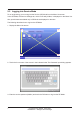
2-2 Logging into Service Mode To run engineering, you must log into the Service (SE) Mode from the Menu List screen. In the SE Mode, the Service Settings tab, which is normally hidden, is displayed on the Menu List. Also, special buttons available only in SE Mode are displayed on the tabs. The following describes how to log into the SE Mode. 1. Display the Menu List screen. (3) (1) (2) (4) 2. Touch the four corners of the screen in the indicated order. The Password Input dialog appears. 3.
Furthermore, if the screen is locked, entering the service password instead of the administrator password after carrying out the special operation indicated below, allows you to unlock the screen and log into the SE Mode.
Names and Functions 3. Detailed Screen Description 3-1 Setup Screen Structure Basic Functions Service Settings Tab (See page 10.) A/C Auto Regist This function automatically registers air conditioners that are not yet registered as management points (See page 10.) Mgmt. Point Data Regist This function allows you to manually register, edit, or delete management points (See page 13.) Other Setting Allows you to configure the error detection level and enable or disable the Dry mode (See page 38.
3-2 Service Settings Tab (1) (2) (3) (4) (5) (6) (8) (9) (10) (11) (12) (13) (7) NOTE The button of an optional function is hidden unless the option is enabled. (1) A/C Auto Regist Automatically registers as management points those air conditioners that are connected to the iTM but not registered as management point. The air conditioner icons to be displayed on the Standard View screen are also set up automatically.
(4) Dealer Option Enables/Disables dealer options. (5) Time Zone Sets up the difference between the Universal Time Coordinated (UTC) and local time. (6) History Mgmt. (Delete) Deletes history records of a specified period from the history. (7) Other Setting Enables/Disables the “Detect Level” and “Dry Operation Mode”. Detect Level: When enabled, indicates management point error alarms via icons and history.
3-3 System Settings Tab (1) (2) (3) (1) Network Sets up the network IP addresses as well as the Web Servers. (2) Web Access Users Sets up Web users for Web Remote Management. (3) Backup Allows you to export the system file and setup data.
Basic Functions 4. Service Settings 4-1 Mgmt. Point Data Regist Register, modify, and delete management points to be controlled using the iTM. Management points can be registered in two ways: directly with the iTM unit, or by editing a CSV file on a PC and loading it to the iTM unit. The figure below shows the flowchart of a management point registration.
The following describes the operating procedure. Registering a management point with the iTM unit 1. Automatically recognizing air conditioners Automatically recognize air conditioners. The iTM unit will search for any D3 units that can be registered, but have not yet been registered with it. Log into SE Mode from the Menu List screen and display the Service Settings tab (see page 7). Touch the Mgmt. Pnt Data Regist button on the Service Settings tab to display the main Mgmt.
For management points whose Detailed Type is unknown, you can select the management point and display the Management Point Types screen by touching the Detailed Type button (4). (5) Using the radio buttons (5), select the management point type. Touch the OK button to save and return to the Auto Search Result screen for air conditioners. (8) (7) (6) Touching the Refresh button (6) updates the Search Result List (7) to its most recent status.
Touch the OK button to register the management point (8) and return to the main Mgmt. Point Data Register screen. NOTE The Add and Add ALL buttons are grayed out when the upper limit of registration has been reached and thus no more management points can be registered. 2. Manually registering management points Register one by one the management points that are not registered by automatic recognition. (9) Touch the Add button (9) to display the Management Point Types screen.
Select the management point type to register from Indoor, Outdoor, Ventilator, Di, and Pi. To select another type, select the Others radio button and touch the Select button. The Management Point Types screen for other types appears. Select the management point type and touch the OK button to save and return to Management Point Types screen. Remark: External Ao or External Pi are not supported by this model. When finished, touch the OK button to display the Mng. Point Attributes screen. 3.
When finished with all the tabs, touch the OK button to save the settings and return to the main Mgmt. Point Data Register screen. 4. Deleting/Editing/Copying a management point (13) (10) (11) (12) Touching the Delete button (10) deletes the management point selected in the list. Touching the Edit button (11) displays the Mng. Point Attributes screen for editing the management point selected in the list.
5. Checking the setting results Touching the Check button (13) checks the content of the current settings data and displays the check results on the Information check screen. If an error is found, discards the edited content retained until then and restores the saved original data. “No error” is displayed if no error is found. Touch the Close button to close the screen. Check items list Classification Check item Message Duplicated ===== Mng.
6. Restarting iTM Restart iTM to reflect the settings. (14) When finished, touch the OK button (14). A settings data check is carried out and the Information check screen displayed if errors are found. If no problems are found, the dialog below appears. Touching the Yes button after confirming restarts the iTM unit.
Detailed Mgmt. Point Attributes screen and button descriptions The following describes the Mng. Point Attributes screen in detail. Tabs and items displayed on the Mng. Point Attributes screen vary depending on the selected management point type. Set up by switching the displayed tabs as necessary. •• Common 1 Tab Sets common items for a management point. Displayed items vary depending on the management point type.
(15) (16) (17) (18) (19) (20) (15) Port No. text field, Address combo box Sets up the port number and address to which the management point belongs. For the port number, touch the Modify button and enter it in the Numerical Input dialog that appears. For the address, select it using the combo box. Duplicated addresses cannot be registered. All addresses must be different.
The range of values you can enter/set is as indicated in the table below.
•• Common 2 Tab Sets up common items 2 for a management point. Displayed items vary depending on the management point type. (21) (22) (22) (21) (22) (21) Prohibit Manual Operation check box Select the check box when prohibiting manual operation from the iTM. (22) Address/ACNSS address text field Sets up the ACNSS address. Touch the Modify button and enter the value in the Numerical Input dialog that appears.
•• Monitoring Tab Sets up the monitoring item. Select either of the communication error monitoring levels: Monitor or Monitor + History by using the radio button. •• Ventilator Tab Sets up the Ventilator. (23) (24) (25) (23) Ventilation Mode check box Select the check box when setting up Fresh Up and/or Auto Air Volume. (24) Fresh Up check box Select the check box to enable Fresh Up. (25) Auto Air Volume check box Select the check box to enable Auto Air Volume.
•• Dio Tab Sets up the Dio. Displayed items vary depending on the management point type. (26) (26) (28) (27) (29) (30) (26) (29) (31) (33) (34) (32) (28) (30) (26) Point Type radio button Select the Di Point Type from A type and B type. (27) Operation Mode radio button Select the Di operation mode from Normal and Equipment error input.
(31) Post-Priority radio button Select whether to allow Start/Stop from the equipment from Enable and Disable. (32) Error output holding radio button Select whether to block the control signal when an error is detected from Enable and Disable. (33) Start-Stop Error radio button Select whether to carry out start/stop error detection from Enable and Disable. (34) Output Contact A/B radio button Select the type of output contact from A type and B type. •• Pulse Tab Sets up the pulse value.
(38) Power Ratio text field Sets up the power ratio. Touch the Modify button and enter the value in the Numerical Input dialog that appears. You can enter a value in the 0.01 to 99999.99 range, in increments of 0.01. For the Internal Pi, the power ratio is fixed to 0.1. (39) Coeff a text field Sets up the coefficient a. Touch the Modify button and enter the value in the Numerical Input dialog that appears. You can enter a value in the 0.000 to 1000.000 range, in increments of 0.001.
•• Analog Tab Sets up the analog value. Displayed items vary depending on the management point type. Analog 1 Analog 2 (41) (45) (46) (42) (47) (43) (44) Analog 1 Analog 2 (48) (41) (42) (43) (44) For the range of values that can be input for each type in the Numerical Input dialog see the table on page 31. (41) Unit Label text field Sets up the unit. Touch the Modify button and enter the value in the Text Input dialog that appears.
(44) Upper Limit field Sets up the upper limit and monitoring status for upper limit error monitoring. For the upper limit, touch the Modify button and enter it in the Numerical Input dialog that appears. For the monitoring status, select from Disable, Monitoring, and Monitor + History from the combo box. (45) Analog Type radio button Select the analog value type from Temperature and Other. (46) Unit Type radio button Select the unit type of External Ai either “Thermistor” or “Other”.
Acceptable range for each numeric value Detailed Type Classification Item Hysteresis Upper/ Lower Lower Limit limit monitoring External Ai Upper BACnet Ai limit Analog value Internal Ai Minimum value Maximum value Hysteresis Upper/ Lower Lower Limit limit monitoring Upper limit Min. of op BACnet Ao Analog value Max.
•• Analog Point Selection Screen Sets up the reference for the Internal Ai. Touch the Ref.. button on the Analog2 tab to display the Analog Point Selection screen. (49) (50) (49) is the list of management points with analog value. (50) is the list of analog values that applicable to the Internal Ai of the selected management point.
Registering management points using a CSV file 1. Outputting a CSV file The current settings data can be output to a CSV file for editing the management point data using a computer software or the Pre-engineering tool. The CSV file can be edited using “Microsoft Excel” and the like. Log into SE Mode from the Menu List screen and display the Service Settings tab (see page 7). Touch the Mgmt. Point Data Register button on the Service Settings tab to display the main Mgmt. Point Data Register screen.
2. Loading a CSV file Load the edited CSV file. The edited data does not overwrite everything, it only merges the difference to the current settings data. Log into SE Mode from the Menu List screen and display the Service Settings tab (see page 7). Touch the Mgmt. Point Data Register button on the Service Settings tab to display the main Mgmt. Point Data Register screen. (52) Connect the USB memory to the iTM unit and touch the Load button (52).
If the setting data has been loaded without any problem, the merge results appear. The Display Merge Results screen consists of the tabs: Add, Modify, Modification Failed, and No change. After checking the list on each tab, touch the Close button to return to the main Mgmt. Point Data Register screen.
Commissioning Manual EM11A021 DCM601A51 intelligent Touch Manager External Di: 1 to 120 External Dio: ON Status Monitor address 1 to 120 Not specified: 0 Normal/Abnormal Monitor Input address 1 to 120 Not specified: 0 ON/OFF operation Start/Stop address 1 Start/Stop address 2 Status Object Type* Status Object Instance* 0 to 4194302, Not used: −1 0 to 4194302, Not used: −1 Normal/Abnormal Monitor BACnet Server Device Instance 0 to 4194302 0 to 1023, Not used: −1 ON Status Monitor Operation Objec
37 Commissioning Manual EM11A021 DCM601A51 intelligent Touch Manager Ventilator Ai/Ao Pi Di/Dio Classification 0: Disable, 1: Enable Start/Stop error ABNORMAL INPUT STARTSTOP FAILURE Correction coefficient b −10.000 to 10.000 CFB See page 31. Hysteresis MARGIN Minimum operation value See page 31. Maximum operation value See page 31. Displayed accuracy (exponent of 10) OPMINVAL OPMAXVAL OPUNIT Fresh up Terminal maximum value See page 31.
NOTE •• Symbols (decimal point, digit group separator, etc) used in Windows may vary depending on the locale. Be sure to check before editing a file. •• Pi pulse value at the time of saving the CSV file is output with an invalid, out of the merge scope value (−1). To enable pulse value merge, rewrite it to a valid range value. •• Daikin recommends you to leave the management point ID in the CSV file in blank so that they are automatically set up at loading.
3. Enable/Disable dry operation mode in Dry Operation Mode (2). When enabled, allows you to set Dry mode from the touch panel, or the Schedule or Interlocking function. Touch the OK button to commit and close the screen. 4-3 DIII-NET Engineering Sets up the iTM as “Main” or “Sub” when also installing an upper central controller. Sets Setpoint Restriction to “Enable” or “Auto” when also installing an upper central controller (such as: Interface for use in BACnet, Interface for use in LONWORKS). 1.
4. (3) is a list of Connector Plugs for each iTM port. (4) is a list of central units recognized on the port selected in (3), where its name is displayed along with its Main/Sub setting. Central units that can be installed together are as follows. NOTE This iTM is not displayed in (4).
4-4 Time Zone Sets up the difference between the Universal Time Coordinated (UTC) and local time. 1. Log into SE Mode from the Menu List screen and display the Service Settings tab (see page 7). Touch the Time Zone button on the Service Settings tab to display the Time Zone Setting screen (see page 10). (1) 2. Select the time zone in the Time Zone area (1). Touching the OK button displays a confirmation dialog. Touch the Yes button to commit and close the screen.
2. (1) is an air conditioner list displaying all Group Addresses. When no management points are registered, columns other than Group Addr. are displayed blank. The displayed contents are as indicated in the table below. Column Group Addr. Name OD-Unit Addr. Changeover Option Err Code Connection Type Displayed information Value range Group address number 1:1-00 to 8:4-15 Displays the name of the Characters permitted by Mgmt. Point Data connected unit. Register.
4-6 History Mgmt. (Delete) Deletes history records. 1. Log into SE Mode from the Menu List screen and display the Service Settings tab (see page 7). Touch the History Mgmt. button on the Service Settings tab to display the History Management screen (see page 10). (1) (4) (2) (5) (3) (6) 2. Using the Remove history data radio button (1), select whether to delete All or a Period. 3. If you selected Period, set up the start date of the period to delete in (2) and the end date in (3).
4-7 Pre-engineering Pre-engineering is carried out to lessen the work to be carried out on site, such as when installing iTM in a large new property, modifying settings due to a large-scale equipment renovation, or making extensive modifications to the settings due to the implementation of new functions, etc.
Relationship between the assumed scenario and functions Function (2) Property data selection Scenario Scenario 1: Installation to new property Scenario 2: Data edit Maintenance of Layout View edit existing property Scenario 3: Restore with existing property’s backup data Pre-engineering tool (3) Property data edit (4) Property data output (3)-2 Layout (3)-1 Restore data Layout settings Data edit output View edit output × × × * Not applicable to iTM integrator × Scenario 4: Implementation of new func
Download the pre-engineering tool from the Distributor’s Page. To use the pre-engineering tool, a separate PC is necessary. The requirements for the PC are as indicated in the table below. PC requirement for running the pre-engineering tool Function Requirement PC to run the pre-engineering tool OS: Windows XP Professional SP3 (32 bit) Windows VISTA Business SP2 (32 bit) Windows 7 Professional SP1 (32 bit, 64bit) CPU: Equivalent to Intel Core 2 Duo 1.
(1) 2. On the login screen that appears, enter the password and click the Login button (1). The iTM Pre-engineering tool main screen appears if the correct password has been provided.
Scenario 1: Installation to new property Set up data for the new property in advance. Main screen (2) 1. Click the New button (2) to display the Create New Folder dialog. Create New Folder dialog (3) (4) (5) 2. Select the location to create the new property’s folder in (3). Clicking the Make New Folder button (4) creates a new folder directly under the folder selected in (3). Clicking the OK button (5) sets up the folder selected in (3) as new folder.
NOTE Clicking the OK button on the confirmation dialog box deletes all folders and files within the folder. Main screen (6) 3. Click the Edit Data button (6) to start up the iTM demo version for PC. Screen of demo version for PC (7) The demo version for PC allows you to make similar settings as with the iTM unit. Make settings as required. When finished, click the 49 button (7) and return to the Pre-engineering tool main screen.
NOTE Input of Activation key (optional functions enable) is not accepted. Main screen (8) 4. Output the edited restore data in the property folder to a USB memory. Click the Export to USB button (8). The Output to USB dialog appears. (10) (9) Select the drive in the Drive combo box (9). Select the content to output using the Output Data radio button (10). Click the OK button. A conformation dialog appears, indicating that you are about to delete the data in the folder.
5. The set up restore data is saved to the USB. Insert the USB memory to iTM to restore. (For details, see 4-10 Installation) NOTE “Layout Setup data only” is available when the Layout option is enabled and saves only the Layout Setup data to the USB memory. For the method of entering the Layout Setup data to the iTM unit, see the supplementary volume Layout View Creation Tool (EM11A024).
Scenario 2: Maintenance of existing property (When carrying out pre-engineering using the current setting) When extensively modifying an existing property due to equipment renovation and the like, the current settings for the existing property must be modified. 1. Back up the system file data as well as settings data, MAC addresses, etc. on the iTM unit to a USB memory. (For details, see 4-9 Backup) 2.
4. Click the Edit Data button (13) to start up the iTM demo version for PC. The steps from editing using the demo version for PC to restore data output to USB and iTM restore are the same as steps 3 to 5 of the procedure for Scenario 1: Installation to new property. NOTE The Layout Setup data backup and restore procedures are the same as when modifying the Layout View of an existing property.
Scenario 3: Restore with existing property’s backup data When iTM in an existing property is replaced due to malfunction and the like, the system is recovered by restoring the backup data (folder name: Backup_MAC address_year month day_hour minute second) to the new iTM. •• iTM Main screen (14) 1. Click the Open button (14) to display the Select Folder to Open dialog. Select the folder of the property for which you are creating the restore data and click the OK button to close the screen. 2.
Scenario 4: Implementation of new functions due to existing property’s upgrade When implementing new functions to an existing property, the upgraded Pre-engineering tool is used to create the functions’ settings data. 1. Back up the system file data as well as settings data, MAC addresses, etc. on the iTM unit to a USB memory. (For details, see 4-9 Backup) 2. Copy data backed up in the USB memory (folder name: Backup_MAC address_year month day_ hour minute second) to a PC.
4-9 Backup When modifying settings data due to equipment renovation in an existing property or upgrade, the iTM unit data must be backed up to a USB memory as history and settings data reference for troubleshooting and the like. Data to be backed up is as follows. •• iTM system file •• Settings data of each function •• Automatically accumulated data such as Energy Navigator’s time tone, trend data, and history data •• MAC addresses NOTE All iTM functions run normally even during backup.
2. Insert a USB memory into iTM. Touching the Backup button (1) displays a backup start confirmation dialog. 3. Touch the Yes button. A USB memory content deletion confirmation dialog appears. 4. Touching the Yes button displays a wait dialog and starts the backup. When backup is complete, an information dialog appears. Touch the Close button to close the screen and remove the USB memory. NOTE •• All the folders and files in the USB memory will be deleted when the backup begin.
4-10 Installation Data installation to the iTM unit includes installation of upgrade data and pre-engineered data (See 4-7 Pre-engineering). The installation procedure is the same in all cases. The following describes the operating procedure. 1. Insert the USB memory with the target data into the iTM unit and turn on, or restart, the iTM unit while pressing the MONITOR button provided on it. Keep the MONITOR button depressed until the following screen appears and then release it.
4. The installation tool screen appears once calibration is finished. NOTE If an error is found in the installer program on the USB memory, an error confirmation dialog appears. Be sure to prepare the correct installer program. (2) (4) (5) (7) (8) (14) (10) (11) (12) (13) (3) (6) (9) 5. The version of the data and MAC addresses in the USB memory are compared with the version and MAC addresses on the iTM. The information displayed on the installation tool screen is as follows.
If there is no flaw in the information, touching the OK button on the installation tool screen starts the installation. When installation is complete, an information dialog appears. Remove the USB memory and touch the Close button to close the screen. The iTM automatically restarts and checks the history and version information, and then installation will be completed.
3. The registered contact information can be checked on the Contact tab of the Information screen accessible from the Standard View screen.
4-12 Setting outdoor unit Set the type of the outdoor unit registered as a Mgmt. point. 1. Log into SE Mode from the Menu List screen and display the Service Settings tab (see page 7). Touch the Outdoor Setup button on the Service Settings tab to display the Outdoor Setup screen (see page 10). (1) 2. Select the desired outdoor unit from the list and touch the (1) Type button. When the input dialogue is displayed, input the type. The type depends on the model of the outdoor unit.
Precautions when using DIII-NET EXPANDER ADAPTER In the application using the DIII-NET EXPANDER ADAPTER, if you monitor the outdoor units or use Internal Pi or such other functions processed based on information from the outdoor units, you need to cut the jumper pin of the DIII-NET EXPANDER ADAPTER. Intended functions: Monitoring of outdoor units, Energy Navigator and leakage detection. The jumper pin to be cut is J1 only. There are two jumper pins to be cut, so be sure to cut both of them.
No. Model name Type No. Model name Type No. Model name Type No.
No. Model name Type No. Model name Type No. Model name Type No.
No. Model name Type No. Model name Type No. Model name Type No.
No. Model name Type No. Model name Type No. Model name Type No.
No. Model name Type No. Model name Type No. Model name Type No.
4-13 Leakage Check Leakage Check is a function available in VRV III or later outdoor units. It checks refrigeration systems for leakage. Leakage Check can be carried our centrally for multiple refrigeration systems installed in a property by sending instructions from the iTM to the outdoor units via DIII-NET. Using the Schedule Control function, you can make the outdoor units run Leakage Check at a specified date and time. You can also run Leakage Check manually on site.
Leakage Check functions Usage scene Category Function Description Registration of Indoor Unit (Page 70) Outdoor unit model type setting Configures the model type of the outdoor unit. (Page 62) Schedule control The instruction to run Leakage Check is sent to the target outdoor unit at the date and time set up using the Schedule Control function. Operation The instruction to run Leakage Check is sent to the target Manual operation outdoor unit right after the command is input.
Touch the Outdoor Setup button on the Service Settings tab to display the Outdoor Setup screen (see page 10). (2) (1) 2. (1) is a list of outdoor units registered in iTM. The Charge item displays the current Refrigerant Charging Operation status for each outdoor unit.
4. (3) is the Registered Indoor Unit list. (4) is the Unregistered Indoor Unit list. Select the indoor unit you want to register and touch the Add button to register. To unregister, select the indoor unit from (3) and touch the Remove button to move it to (4). The indoor unit becomes unregistered. Touch the OK button to commit the indoor unit registration and close the screen. Running Leakage Check by Schedule Control Set up a schedule program to run Leakage Check. (5) (6) 1.
2. The management point name of the target outdoor unit appears in the Name field (7). You may set up to four schedule programs per outdoor unit. Enable/disable the schedule program in (8). Set up the Leakage Check start date in (9). Touch the Modify button and enter the time in the Time Input dialog that appears. The range of values you can specify is January 1, 2010 to December 31, 2036. (10) displays the start time. Touch the Modify button and enter the time in the Time Input dialog that appears.
Copying a schedule program 1. You may set the same program set up in the Schedule Setup screen to another outdoor unit. (11) Touch the Schedule Copy button (11) to display the Copy screen. (12) (13) (14) 2. The name of the outdoor unit source of copy appears in the Copy from field (12). Display the name of the outdoor unit destination of copy in the Copy to list (13). The Available list (14) is a list of outdoor units that can be registered as copy destination.
Starting Leakage Check by manual operation Start Leakage Check by manual operation. (15) (16) 1. Select the target outdoor unit from the Outdoor Unit list (15) and touch the Check Start button (16). A confirmation dialog appears. Touching the Yes button starts a check to determine whether the statuses of the target outdoor unit and indoor units registered in the refrigeration system of the outdoor unit are suitable for starting Leakage Check. If they are in normal status, the Leakage Check starts. 2.
NOTE Executing a Leakage Check places the outdoor unit and indoor units registered in the same refrigeration system under “Maintenance”. “Maintenance” is released upon Leakage Check completion (If the iTM is stopped when the Leakage Check completes, “Maintenance” is released at power recovery). After staring Leakage Check, check that an appropriate indoor unit is “Under Maintenance”.
Outputting the Leakage Check results to a CSV file Output the Leakage Check results to a CSV file. (19) (20) 1. Insert a USB memory into the iTM and touch the CSV Output button (20). A confirmation dialog appears. Touching the Yes button outputs to the USB memory the Leakage Check results for all outdoor units registered in the Outdoor Unit list (19) as a CSV file named LeakageCheck.csv.
NOTE •• The calculated leakage amount is only a guide. •• The check result may not be correct if the power is lost during leakage check. CAUTION •• Leakage check may fail depending on the room temperature. Moderate the room temperature by conducting the cooling or heating operation before starting leakage check. * Recommended temperature Room temperature: 22°C – 30°C Outdoor temperature: 5°C – 35°C •• The indoor unit stops after a leakage check.
Conflict with other controls The following describes the operation when another control comes into conflict with the Leakage Check. : Enabled ×: Disabled Target management point Outdoor unit Communication status System Indoor unit * Leakage Check Other control Communication error × Central Stop Monitoring Start operation Equipment error × × × Communication error System Settings modifications from the Maintenance Setup screen is not allowed during Leakage Check.
NOTE •• Inform the user that all units are forced to operate in the cooling mode during leakage check. •• Caution the user not to change the time setting of iTM during leakage check. •• Power consumed by the indoor unit during leakage check is also proportionally distributed. •• Leakage check and power limit control (*) cannot be conducted at the same time. (i) If power limit control is set to [Demand 3(Forced thermo OFF)], it will be conducted before leakage control.
Failure mode The following describes the failure modes of the Leakage Check.
Handling Scene Failure mode Impact to users Cause Notification method When Leakage Check instruction Manual Check Start failure Leakage Check cannot be run •• Outdoor units are under maintenance •• Outdoor units are communication error •• Outdoor units are auto charge not completed •• Indoor units are equipment error •• Indoor units are under maintenance •• Indoor units are in emergency stop Scheduled Check Start failure Leakage Check cannot be run iTM judged that it successfully started Leakag
Handling Scene During Leakage Check Leakage Check results acquisition 83 Failure mode Impact to users Cause Indoor units are under maintenance Notification method When How At emergency stop signal generation •• The emergency stop signal is sent and indoor units emergency stopped Recovery method Emergency Stop signal has been received during Leakage Check Emergency stop cannot stop indoor units Time has been modified during Leakage Check None — Judgment is possible because the results are v
Optional Functions 5. Service Settings 5-1 Activation In addition to standard functions, iTM provides various optional functions suited to users’ needs. There are two types of optional functions: optional maker functions sold by Daikin Industries, Ltd. and dealer options sold by dealers. This chapter describes the procedure to activate optional maker functions. Acquiring the Activation key To activate an optional maker function, you must acquire the Activation key before making settings on site.
(1) (2) (3) 2. The MAC address of the iTM unit appears in MAC Address (1). (2) is a list of currently enabled optional maker functions. 3. To enable a new optional maker function, touch the Add button (3). Enter the Activation key for the optional maker function using the text input keyboard that appears and touch the OK button. If the key is correct, the function is added to the list (2). 4. Touch the OK button on the Activation Setup screen.
5-2 Dealer Option Setup The following describes the procedure to enable dealer options. 1. Log into SE Mode from the Menu List screen and display the Service Settings tab (see page 7). Touch the Dealer Option Switch button on the Service Settings tab to display the Dealer Option screen (see page 10). (1) (2) Enable (1) is a list of enabled dealer options. Disable (2) is a list of disabled dealer options. 2. To enable a new optional function, select it from (2) and touch the Add button.
Operating Optional Functions 6. System Settings 6-1 Network iTM allows you to operate it remotely via the Internet, or receive notification via E-mail in the case of an error. To use these functions, you must set up the network on the iTM unit. The following describes how to set this up. 1. Touch the Network button on the System Settings tab of the Menu List screen to display the Network screen (see page 12).
2. The current settings are displayed. Touch the Modify button to modify the settings in the Input dialog that appears. For information necessary for the settings, consult your network administrator. (1) Controller name (2) Host name (3) IP address (4) Subnet mask (5) Default gateway address (6) Preferred DNS address (7) Alternate DNS address 3. Set up the Web server port number. (8) Touch the Web Server button (8) to display the Web Server screen and set up the port number.
(9) (10) Select (9) to use the default port 80. Selecting (10) displays the port number 8080. Touching the Modify button allows you to modify the settings in the Numerical Input dialog that appears. Touch the OK button to save and close the screen. 4. When finished, touch the OK button. A confirmation dialog appears. 5. A restart confirmation message is displayed. Touch the Yes button to reflect the setting and restart the iTM.
6-2 Web Remote Management The iTM can be remotely operated via the Internet or local network. Ethernet (100Base-T or higher) PC (Web browser) iTM PC (Web browser) Internet Firewall For settings necessary on the iTM unit, see “6-1 Network”. This chapter describes the PC setup procedure. To use the Web Remote Management functions, you need to separately prepare a PC and software such as a Web browser. The requirements for the PC are as indicated in the table below.
Connecting the PC and iTM Connect the PC and iTM unit into a network using an Ethernet cable. Ethernet cables use for connecting networks come in two types: straight and cross. Connect the PC and iTM unit by referring to the connection diagrams below. Straight cable connection diagram Cross cable connection diagram When connecting the PC and iTM directly: Use a 100Base-TX or higher Ethernet cross cable.
Checking the Web browser and Flash Player versions 1. Start up the Web browser (Internet Explorer) and select [About] from the [Help] menu. NOTE In the case of Firefox, you can check by selecting [Help] → [About Mozilla Firefox]. Check that the version is 8.0.xxxx.xxxxxxx or 9.0. xxxx.xxxxxxx. (The xxx portion may be any) 2. Enter the address of the site for checking the Flash Player version: http://www.adobe.
Check that the version is 11.1.xxx.xx. (The xxx portion can be any) Operation cannot be guaranteed if both the Web browser and Flash Player are not of the specified version. Be sure to use the version described in the table. NOTE Necessary software can be downloaded from Microsoft, Adobe, and other sites for free. Setting up the IP address (Windows XP Professional) 1. Select [Start] → [Control Panel]. 2. Click [Network and Internet Connections].
3. Click [Network Connections]. 4. Double click [Local Area Connection].
5. Select [Properties]. 6. Select [Internet Protocol (TCP/IP)] and click [Properties].
7. To connect to the iTM via the Internet, ask its IP address and subnet mask to your network administrator and set them up. Set them up as follows when connecting to the iTM via local network. IP address: 192.168.0.2 Subnet mask: 255.255.255.0 NOTE iTM settings at shipment are as follows. Item Settings at shipment Host name localhost IP address 192. 168. 0. 1 Subnet mask 255. 255. 255. 0 Default gateway 0. 0. 0. 0 Preferred DNS 0. 0. 0. 0 Alternate DNS 0. 0. 0.
Setting up the IP address (Windows Vista Business) 1. Select [Start] → [Control Panel]. 2. Click [Network and Internet]. 3. Click [Network and Sharing Center].
4. Click [Manage network connections]. 5. Double click [Local Area Connection].
6. Click [Properties]. 7. Select [Internet Protocol Version 4 (TCP/IPv4)] and click [Properties].
8. To connect to the iTM via the Internet, ask its IP address and subnet mask to your network administrator and set them up. Set them up as follows when connecting to the iTM via local network. IP address: 192.168.0.2 Subnet mask: 255.255.255.0 NOTE For iTM settings at the time of shipment, see page 96. 9. Check that the settings are correct and click [OK] to close the [Internet Protocol Version 4 (TCP/ IPv4) Properties] and [Local Area Connection Properties] screens.
Setting up the IP address (Windows 7 Professional) 1. Select [Start] → [Control Panel]. 2. Click [Network and Internet]. 3. Click [Network and Sharing Center].
4. Double click [Local Area Connection]. 5. Select [Properties].
6. Select [Internet Protocol Version 4 (TCP/IPv4)] and click [Properties]. 7. To connect to the iTM via the Internet, ask its IP address and subnet mask to your network administrator and set them up.
Set them up as follows when connecting to the iTM via local network. IP address: 192.168.0.2 Subnet mask: 255.255.255.0 NOTE For iTM settings at the time of shipment, see page 96. 8. Check that the settings are correct and click [OK] to close the [Internet Protocol Version 4 (TCP/ IPv4) Properties] and [Local Area Connection Properties] screens. Click [Close] to close the [Local Area Connection Status] screen and finish setup.
(1) (2) (3) (4) (5) Network Connection Check Check whether the Ethernet connection between a PC and iTM is normal. Carry out the following procedure from the PC.
1. From the Start menu of the PC, select “All Programs” → “Accessories” → “Command Prompt”. Alternatively, select “Run” from the Start menu of the PC, enter “cmd” in Open and click the OK button.
2. The command prompt starts up. Type “ping” followed by one single byte space and then the iTM IP address, and press the Enter key. (In this example, the IP address is 192.168.0.
3. If Lost=0(0% loss) is displayed, the Ethernet connection between the PC and the iTM unit is normal. If Lost=4(100% loss) is displayed, then the PC could not recognize the iTM unit. Check the settings. NOTE When a port number is set up in the network settings of the iTM unit, enter “:” followed by the port number after the IP address. (Example: If port number is 8080, enter 192.168.0.
iTM integrator Explanation 7. iTM integrator 7-1 Basic Setup If you are sure that all connections have been made, proceed to the basic setup of the iTM integrator. Here, “basic setup” means setting up the iTM integrator in preparation for controlling the operation of your air conditioning system. Turning on the power of the iTM integrator starts a setup program that lets you complete the basic setup procedure.
Select Basic software and enter the MAC address, Software ID, and User information of the iTM integrator you want to install. Write down the activation key that appears on the screen. 3. Powering on data backup battery To retain the settings even in the event of a power outage, the iTM integrator has a built-in battery. Because this battery is disabled by default, the first thing you should do is to enable it. Open the front slide cover and turn the screws to remove the front slide cover.
5. Setting up display language Set up the display language used throughout the iTM integrator setup screens. 1. Touch the desired language from those listed on the screen. The radio button next to the language you touched is now selected. 2. Touch OK. The Locale Settings screen appears. NOTE If the message “Turn ON Battery Backup switch” appears instead of the Locale Settings screen, it means that you did not turn on the data backup battery.
6. Setting up locale “Locale setup” allows to set up how you want to see items that are expressed in different ways depending on the region, such as the data/time, temperature, and decimal point, on the display. 1. [LOCALE] Select the desired options on the Locale Settings screen. [Language] Select the display language. [Date] Select the date display format. [Time] Select the time display format (24-hour or 12-hour clock).
7. Setting time zone Set up the local standard time zone you want to use for the system clock.
7-2 iTM integrator Service Settings Set up the iTM integrator unit. iTM integrator Web Remote Management USB port USB memory Power (100 240V) LAN port Internet Internet Web Remote Management Router HUB Individually working as iTM* 100Base-TX compliant iTM iTM iTM iTM iTM 5 units connected Service settings described in this chapter are for the iTM integrator unit.
Service Settings Tab (Menu List Screen) Displayed when you log into Service Mode from the iTM integrator Menu List screen. The procedure to log into Service Mode is the same as that for the iTM. See “2-2 Logging into Service Mode”. (1) (2) (3) (4) (1) Time Zone Sets the difference between the Universal Time Coordinated (UTC) on the iTM integrator and the local time. The setup method is the same as that for the iTM. See “4-4 Time Zone”. (2) History Mgmt.
Controller Access Setup Set up the connection between the iTM to be controlled and the iTM integrator. 1. Display the Service Settings tab on the iTM integrator Menu List screen. (1) 2. Touch the Controller Access button (1) to display the Controller Access Setting screen.
(2) 3. Touch the Add button (2) to display the Controller screen. (3) (4) 4. Touch the Modify button (3) and enter the iTM IP address in the IP Address Input dialog that appears. Set up the iTM Web port number in (4). Select Default or User Setup using the radio button. If you selected User Setup, then touch the Modify button to enter it in the Numerical Input dialog that appears.
Possible value range Value at shipment Initial value at new registration “1 to 223(*)”.“0 to 255”.“0 to 255”.“0 to 255” * Addresses starting with “127” cannot be set up since they are for loopback. — 192.168.0.1 — Default: 80 Item IP address set up in controller Default: 80 Web server port number User Setting: 1024 to 65535, in set up in controller increments of 1 5. When finished, touch the OK button to return to the Controller Access Setting screen.
6. When finished, touch the OK button to close the screen. If there is an iTM whose connection status is “Disconnected”, the following Confirm dialog appears. To exit setup leaving the iTM disconnected, touch the Yes button. To return to the Controller screen, touch the No button. 7. Open and close all the Layout Views of iTM.
Appendix 8. Useful Information 8-1 Troubleshooting Troubleshooting table Remote operation DIII-NET Problem Checking method Cannot remotely operate iTM from the PC. When iTM and PC are connected via hub, check whether they are correctly connected. Cause Measure PC is not connected with iTM. Connect the iTM and PC via hub using LAN cables. Cross cables are used as the LAN cable for connecting the iTM and PC via hub. Use straight cables as LAN cable for connecting the iTM and PC via hub.
Air conditioner control PPD Problem Checking method Air conditioners continue to work in cool mode though the room temperature is lower than the lower limit set up by the Temperature Limit function. Check whether the subject indoor units have Changeover Option. The subject indoor units are controlled by an upper unit with Changeover Option. Check the Temperature Limit settings.
9. Hardware Specifications 9-1 iTM Hardware Specification 207mm 243mm 256.6mm 290mm Power AC100 - 240 V 50/60 Hz Power consumption 23 W Emergency stop input Always “a” contact Contact current approximately 10 mA Size 290 × 243 × 50 (W × H × D) Weight 2.4 kg Time accuracy Within −195.7 to 79.
Peripheral Equipment Specification Function PC for Web Remote Requirement OS: Windows XP Professional SP3 (32 bit) Management Windows Vista Business SP2 (32 bit) PC for pre-engineering tool Windows 7 Professional SP1 (32 bit, 64bit) CPU: Equivalent to Intel Core 2 Duo 1.2 GHz or higher Memory: 2 GB or more Free HDD space: 10 GB or more Network: 100Base-TX or higher Display resolution: 1024 x 768 or higher Network 100Base-TX Real transfer rate: 115 kbps or higher USB memory USB2.
EM11A021 (1208) HT