
Specifications

SiBE341027 Field Setting from Outdoor Unit
Test Operation 83
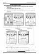
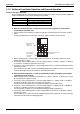
Supplementation on e and f.
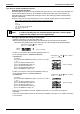
When switching cool/heat for each adaptor PCB with the use of more than one adaptor PCB, set the address
of the external control adaptor for outdoor unit PCB DS1 and DS2
so that it matches the unified cool/heat
address of outdoor unit main PCB.
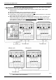
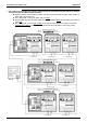
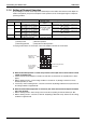
Address setting for
e
and
f
(Set lower 5 digits with binary number.) [No.0 to No.31]
External
control adaptor
for outdoor unit
No.0
C/H unified address
C/H unified address
Outdoor
unit unified
master No.0
Outdoor
unit unified
slave No.0
Outdoor
unit unified
slave No.0
External
control adaptor
for outdoor unit
No.2
C/H unified address
Outdoor
unit unified
master No.2
Outdoor
unit unified
slave No.2
Outdoor
unit unified
slave No.2
External
control adaptor
for outdoor unit
No.1
Outdoor
unit unified
master No.1
Outdoor
unit unified
slave No.1
C/H unified address
External
control adaptor
for outdoor unit
No.3
Outdoor
unit unified
master No.3
Outdoor
unit unified
slave No.3
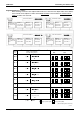
Address
No.
No 0
No 1
No 2
No 3
No 4
No 30
No 31
Outdoor unit PCB LED
Set with setting mode 2
External control adaptor for outdoor unit
DS2
DS1
kh hhhhh
kh hhhhk
kh hhhkh
kh hhhkk
kh hhkhh
kh hhhhk
kh kkkkk
0
1
2
3
4
30
31
0
1
2
3
4
30
31
~
~
~
k ON h OFF
Upper position (ON) lower position (OFF)
(The shaded part shows knob)
(V2724)