
Specifications

SiBE341027 Field Setting from Outdoor Unit
Test Operation 81
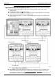
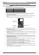
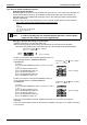
e Set Cool / Heat for More Than One Outdoor Unit System Simultaneously in Accordance with Unified
Master Outdoor Unit by Indoor Unit Remote Controller
Install the external control adaptor for outdoor unit on either the outdoor-outdoor, indoor-outdoor
transmission line.
Set outdoor unit PCB DS1-1 to IN (factory setting).
In setting mode 1, set the outdoor unit you want to give cool/heat selection permission to as the unified
master, and set the other outdoor units as unified slave units.
Set the external control adaptor for outdoor unit SS1 to BOTH (factory setting) or C/H, and SS2 to OFF
(factory setting).
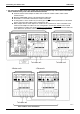
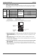
Multi outdoor units connection
When multiple external control adaptors for outdoor unit are used and cool / heat is selected for each
external control adaptor for outdoor unit, use “setting mode 2” and set DS1 and DS2
on the external
control adaptors for outdoor unit and the unified cool / heat address
on the outdoor unit main PCB to the
same address No. (For details, refer to the following page.)
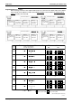
External control adaptor for outdoor unit
C/H SELECT
C/H SELECT
C/H SELECTOR
C/H SELECT
IND MASTER SLAVE
IND MASTER SLAVE
MODE
TEST
L.N.O.P.
DEMAND
MODE
TEST
L.N.O.P.
DEMAND
CENTRAL
C/H
SELECTOR
OFF ON
BOTH C/H DE
FUNCTION
CENTRAL
NO.
TERMINAL
ADDRESS
C/H
OUT-MULTI
OUT
IN
C/H SELECT
C/H SELECT
C/H SELECTOR
IND
MASTER SLAVE
MODE
TEST
L.N.O.P.
DEMAND
OUT-MULTI
OUT
IN
C/H SELECT
C/H SELECTOR
OUT-MULTI
OUT
IN
Multi
C/H SELECT
C/H SELECT
C/H SELECTOR
IND
MASTER
SLAVE
MODE
TEST
L.N.O.P.
DEMAND
OUT-MULTI
OUT
IN
Multi
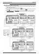
<Master unit>
To indoor unit
To indoor unit
<Slave unit>
To indoor unit