
Specifications

SiBE341027 Troubleshooting by Remote Controller
Service Diagnosis 157
Troubleshooting
Caution
Be sure to turn off power switch before connect or disconnect connector,
or parts damage may be occurred.
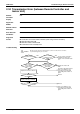
YES
NO
NO
YES
NO
YES
YES
YES
YES
YES
NO
NO
NO
NO
YES
NO
NO
NO
YES
YES
NO
YES
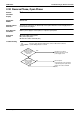
(
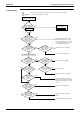
Go on to the next page.
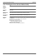
LED lamp display
)
Check the detailed error
status in the monitor mode.
Reset the power supply.
In Confirmation of
error 4, LED lamp
indicates as follows:
Check if indoor unit PCB or
outdoor unit PCB has been
replaced. Or check if
indoor/outdoor, outdoor/ outdoor
connecting wires has been
modified.
Do all the indoor remote
controllers within the
same refrigerant circuit
display “
U4”?
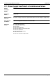
Are the indoor/
outdoor, outdoor/
outdoor connecting
wires normal?
Is the voltage between
R, S terminals on the
outdoor unit PCB
400V?
Is the fuse on the
outdoor unit PCB
blown?
Does the normal
condition monitor for the
micro-computer (HAP)
on the outdoor unit PCB
blink?
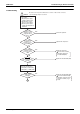
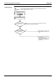
Does the LED in
preparation mode (H2P) on
the outdoor unit PCB
blink?
Lights do not go
out for 12
minutes or
more.
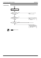
Are the indoor/
outdoor, outdoor/
outdoor connecting
wires normal?
Check if the operation is
normal with 1 circuit after
outdoor/outdoor connecting
wires are disconnected.
Press the RESET button on the
main PCB of the master outdoor
unit. Keep pressing for 5 seconds
or more. (Operation does not start
for a maximum 12 minutes.)
Replace the indoor unit PCB.
Correct the connecting wires.
Correct the voltage (400V).
Replace the fuse.
Replace the outdoor unit PCB.
Press the RESET button on the
main PCB of the outdoor unit main
PCB. Keep pressing for 5 seconds
or more.
Correct the connecting wires.
Replace the outdoor unit main
PCB.
Install DIII-Net extension adaptor.