
Specifications

Troubleshooting by Remote Controller SiBE341027
102 Service Diagnosis
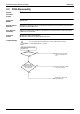
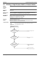
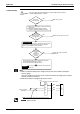
<Monitor mode>
To enter the monitor mode, press the
MODE (BS1) button when in “Setting
mode 1”.
<Selection of setting item>
* Refer to P. 77 for Monitor mode.
* Refer to P. 77 for Monitor mode.
Press the SET (BS2) button and set
the LED display to a setting item.
<Confirmation of error 1>
Press the RETURN (BS3) button
once to display "First digit" of error
code.
<Confirmation of error 2>
Press the SET (BS2) button once to
display "Second digit" of error code.
<Confirmation of error 3>
Press the SET (BS2) button once to
display "error location".
<Confirmation of error 4>
Press the SET (BS2) button once to
display "master or slave 1 or slave 2
or slave 3" and "error location".
Detail
description
on next
page.
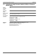
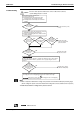
Press the RETURN (BS3) button and
switches to the initial status of
“Monitor mode”.
* Press the MODE (BS1) button and
returns to “Setting mode 1”.
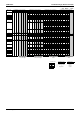
Error Error code
Description of error Description of error (PGF) Remote
controller
Inverter PCB abnormality Defective IPM L1
Current sensor error confirmation 1
Current sensor error confirmation 2
IGBT error
Inverter radiation fin temperature rise Overheat of INV. radiation fin
temperature
L4
Momentary overcurrent of INV.
compressor
L5
Overcurrent abnormal of INV.
compressor
Electric thermal and others L8
INV. compressor starting abnormality Stall prevention L9
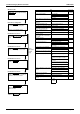
Transmission system abnormality
(between INV. and main PCB)
INV. transmission data abnormality LC
INV. transmission abnormality
Inverter over-ripple protection Unbalanced INV. power supply
voltage
P1
INV. radiation fin thermistor and
related abnormality
INV. fin thermistor abnormality P4
Field setting abnormality after
replacing main PCB or combination
error of PCB
Defective combination of INV. PJ
Refrigerant shortage U0
Reverse phase, open phase Reversed phase U1
Reversed phase (ON)
Power supply insufficient or
instantaneous failure
Insufficient INV. voltage U2
INV. open phase (single phase)
Abnormal charge of capacitor of INV.
main circuit
Check operation is not completed. Test operation not carried out yet U3
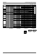
Transmission error (between indoor
and outdoor units)
IN-OUT transmission error U4
System error
Transmission error (between remote
controller and indoor unit)
U5
Transmission error (Across outdoor
units)
Error caused when mounting the
external control adaptor for outdoor
unit
U7
Alarm given when mounting the
external control adaptor for outdoor
unit
Error caused between the master and
the slave 1
Error caused between the master and
the slave 2
Defective address setting of slaves 1
and 2
Erroneous address of slaves 1 and 2
Improper combination of indoor and
outdoor units, indoor units and remote
controller
Excess indoor units connected UA
Connection of erroneous models of
indoor unit
Combination error of outdoor units
Transmission error (between
centralized controller and indoor unit)
UE
System is not set yet Unmatched wiring/piping UF
System, refrigerant system address
undefined
Wrong wiring (auto address error) UH
k
: ON
l
: Blink
h
: OFF