
Specifications
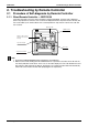

Troubleshooting by Remote Controller SiBE341027
100 Service Diagnosis
Error code indication by outdoor unit P
C
B
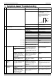
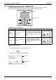
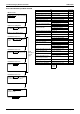
<Monitor mode>
To enter the monitor mode, press the
MODE (BS1) button when in “Setting
mode 1”.
<Selection of setting item>
* Refer to P. 77 for Monitor mode.
* Refer to P. 77 for Monitor mode.
Press the SET (BS2) button and set
the LED display to a setting item.
<Confirmation of error 1>
Press the RETURN (BS3) button
once to display "First digit" of error
code.
<Confirmation of error 2>
Press the SET (BS2) button once to
display "Second digit" of error code.
<Confirmation of error 3>
Press the SET (BS2) button once to
display "error location".
<Confirmation of error 4>
Press the SET (BS2) button once to
display "master or slave 1 or slave 2
or slave 3" and "error location".
Detail
description
on next
page.
Press the RETURN (BS3) button and
switches to the initial status of
“Monitor mode”.
* Press the MODE (BS1) button and
returns to “Setting mode 1”.
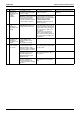
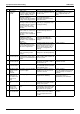
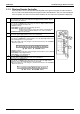
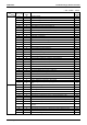
Error Error code
Description of error Description of error (PGF) Remote
controller
PCB abnormality Defective PCB E1
Abnormal discharge pressure or field
piping pressure
HPS or PS activated E2
High pressure abnormality High pressure switch activated E3
Actuation of low pressure sensor Defective Pe E4
Inverter compressor motor lock INV compressor lock detected E5
STD compressor motor overcurrent/
Lock
STD 1 E6
STD 2
Outdoor unit fan motor abnormality Defective fan motor 1 E7
Defective fan motor 2
Electronic expansion valve coil
abnormality (Y1E-Y3E)
Y1E (Main) E9
Y2E (Refrigerant charging)
Y3E (Subcool heat exchanger)
Abnormal discharge pipe temperature Defective Td F3
Refrigerant overcharge Abnormal heat exchanger
temperature
F6
High pressure switch system
abnormality
H3
Abnormal outdoor fan motor signal Fan motor 1 positioning signal H7
Fan motor 2 positioning signal
Thermistor abnormality Thermistor (Outdoor air) H9
High pressure sensor abnormality Defective high pressure sensor J1
Current sensor abnormality STD 1 J2
STD 2
Thermistor abnormality (discharge
pipe)
For INV. compressor J3
For STD 1 compressor
For STD 2 compressor
Thermistor abnormality (suction pipe) TsA sensor malfunction (short-
circuited)
J5
Thermistor abnormality (heat
exchanger deicer)
Tb sensor malfunction J6
Thermistor abnormality (liquid pipe) Tsc sensor malfunction J7
TL sensor malfunction
Thermistor abnormality (receiver
liquid level, refrigerant regulator liquid
pipe, Receiver gas vent outlet)
Tf sensor malfunction J8
Thermistor abnormality (subcooling
heat exchanger outlet)
Tsh sensor malfunction J9
High pressure sensor abnormality Defective high pressure sensor JA
Low pressure sensor abnormality Defective low pressure sensor JC
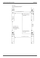
k
: ON
l
: Blink
h
: OFF