
Installation manual


9 English
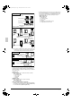
Pipe Sizes Selection
Piping between Outdoor Unit ~ Refrigerant Branch Connection (Part A)
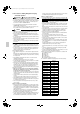
Calculation Method of Re-charging Amount of
Refrigerant
Re-charging Amount R (kg)
( • Round off at 2 places of decimals for R.)
NOTE:
THE ADDITIONAL REFRIGERANT CHARGING AMOUNT BEFORE TEST
RUN IS ONLY CORRECTION VALUE BY OUTDOOR UNIT CAPACITY.
(unit:mm)
R= +
+
+ +
+
R= 45 0.18 + 23 0.12 + 195 0.059 + 40 0.022 + 2.8 =26.045
i+ra+b c+d+e+f+g+h+s
26.0 kg
×0.37
+
Example for refrigerant branches using REFNET joints and REFNET headers
j+k Q22 type
< for individual systems >
< for multi-connecting systems >
Indoor unit
Indoor unit
Outdoor unit
Outdoor unit
Part D
Part D
Part E Part A Part B Part C
Part E
Part A
• Select from below chart according to system name of the outdoor unit.
• When equivalent piping length between outdoor unit ~ indoor unit is 90m or
longer, sizes of main pipes on the gas and liquid sides (Part A) must be
enlarged.
Piping between Refrigerant Branch Connection ~ Indoor Unit (Part E)
• Match to the size of the connection piping on the indoor unit.
*1 Existing pipes must meet the condition of design pressure 3.3MPa.
Specificly, to confirm that the (pipe) thickness must not be less than the
required minimum thickness instructed in the installation manual (1).
*2 Existing pipes must be connected at Part A.
Piping between Outdoor unit multi Connection Piping kit (Part B)
• Select from below chart according to individual capacity type of constructing
outdoor unit.
Piping between Outdoor unit multi Connection Piping Kit ~ Outdoor Unit (Part C)
• Select from below chart according to individual capacity type of constructing
outdoor unit.
Q8 type
Q10 type
Q12 type
Q14 type
Q16 type
Q18~22 type
Q24 type
Q26~34 type
Q36~48 type
φ19.1
φ22.2
φ28.6
φ34.9
φ41.3
φ28.6
φ34.9
φ41.3
φ54.1
φ9.5
φ12.7
φ15.9
φ19.1
φ15.9
φ19.1
φ22.2
System name of
outdoor unit
gas pipe liquid pipe
standard size
max. size
standard size
max. size
[gas side]
Q8 type : φ19.1 → φ22.2
Q10 type : φ22.2 → φ25.4*
Q12, 14 type : Not lncreased
Q16~22 type : φ28.6 → φ31.8
Q24 type : Not lncreased
Q26~34 type : φ34.9 → φ38.1
Q36~48 type : Not lncreased
[liquid side]
Q8, 10 type : φ9.5 → φ12.7
Q12~16 type : φ12.7 → φ15.9
Q18~24 type : φ15.9 → φ19.1
Q26~48 type : φ19.1 → φ22.2
* If available on the site, use this size.
Otherwise it can not be increased.
Piping between Refrigerant Branch kits (Part D)
• Select from below chart according to total capacity of indoor units connected
down-stream.
(Note)
Sizes of connection pipings must not exceed main pipe sizes (Part A).
(unit:mm)
< 150
150 ≤ x < 200
200 ≤ x < 290
290 ≤ x < 420
420 ≤ x < 640
640 ≤ x < 920
920 ≤ x
φ15.9
φ19.1
φ22.2
φ28.6*
φ34.9
φ41.3
φ19.1
φ25.4
φ28.6
φ34.9
φ54.1
φ9.5
φ12.7
φ15.9
φ19.1
φ12.7
φ15.9
φ19.1
φ22.2
Total capacity of
indoor units
gas pipe liquid pipe
standard size
max. size
standard size
max. size
(unit:mm)
P20 · 25 · 32 · 40 · 50 type
P63 type *φ12.7 appliable
P80 type
P100 · 125 · 140 type
P200 type
P250 type
φ12.7
φ15.9*
φ15.9
φ19.1
φ22.2
φ15.9
φ19.1
φ25.4
φ28.6
φ6.4
φ9.5
φ9.5
φ12.7
Capacity type of
indoor unit
gas pipe liquid pipe
standard size
max. size
standard size
max. size
total length (m)
of liquid pipe
size at
φ22.2
×0.022
total length (m)
of liquid pipe
size at
φ6.4
×0.26
total length (m)
of liquid pipe
size at
φ19.1
×0.18
total length (m)
of liquid pipe
size at
φ15.9
×0.12
total length (m)
of liquid pipe
size at
φ12.7
×0.059
total length (m)
of liquid pipe
size at
φ9.5
Q8 0kg Q18 0.7kg Q28 4.1kg Q38 4.8kg Q48 6.0kg
Q10 0.7kg Q20 2.1kg Q30 3.7kg Q40 6.2kg
Q12 2.1kg Q22 2.8kg Q32 4.0kg Q42 4.7kg
Q14 1.7kg Q24 4.2kg Q34 2.7kg Q44 6.1kg
Q16 2.0kg Q26 2.7kg Q36 4.1kg Q46 5.7kg
(Example)
When outdoor unit is Q22
type and each piping
length is as right.
a : φ15.9 × 40 m
b : φ15.9 × 5 m
c : φ9.5 × 35 m
d : φ9.5 × 35 m
e : φ9.5 × 35 m
f : φ9.5 × 35 m
g : φ9.5 × 30 m
h : φ9.5 × 20 m
i :φ12.7 × 20 m
j : φ6.4 × 20 m
k : φ6.4 × 20 m
r : φ12.7 × 3 m
s : φ9.5 × 5 m
∗Note 1
Allowable length after the first refrigerant branch kit to indoor units is 40 m or less, however it can be extended up to 90 m if all the following conditions are satisfied. (In case of “ Branch with REFNET joint ” )
* If available on the site,
use this size.
Otherwise it can not be
increased.
Required Conditions Example Drawings
1. It is necessary to increase the pipe size if the pipe length between the first branch
kit and the final branch kit is over than 40m. (Reducers must be procured on site)
If the increased pipe size is larger than main pipe size, then increase the main pipe
size to the same pipe size.
4. The difference between
[Outdoor unit to the farthest indoor unit] and [Outdoor unit to the nearest indoor unit]
≤ 40 m
2. For calculation of Total extension length, the actual length of above pipes must be
doubled. (except main pipe and the pipes that are not increased)
3. Indoor unit to the nearest branch kit ≤ 40 m
8 b+c+d+e+f+g+p≤ 90 m
increase the pipe size of b, c, d, e, f, g
a+b×2+c×2+d×2+e×2+f×2+g×2
+h+i+j+k+l+m+n+p≤ 300 m
h, i, j....... p ≤ 40 m
The farthest indoor unit 8
The nearest indoor unit 1
(a+b+c+d+e+f+g+p)-(a+h)≤ 40 m
Increase the pipe size as follows
φ 9.5 → φ12.7
φ12.7 → φ15.9
φ15.9 → φ19.1
φ19.1 → φ22.2
φ22.2 → φ25.4*
φ28.6 → φ31.8*
φ34.9 → φ38.1*
a
ABCDEFG
bcdef
g
hi j kl mn
1234567
8
H1
p
Outdoor unit
REFNET joint (A-G)
Indoor units ( 1 - 8 )
*φ25.4 applicable in case of 290 ≤ x <420, if available on the site.
Correction value by outdoor unit capacity
01_EN_3P226891-13Q.fm Page 9 Thursday, December 2, 2010 10:15 AM