00_CV_3P226891-13Q.
00_CV_3P226891-13Q.
00_CV_3P226891-13Q.
00_CV_3P226891-13Q.
00_CV_3P226891-13Q.
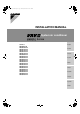
01_EN_3P226891-13Q.fm Page 1 Thursday, December 2, 2010 10:15 AM RQYQ8PY1B RQYQ10PY1B RQYQ12PY1B RQYQ14PY1B RQYQ16PY1B RQYQ18PY1B RQYQ20PY1B RQYQ22PY1B RQYQ24PY1B RQYQ26PY1B RQYQ28PY1B RQYQ30PY1B RQYQ32PY1B RQYQ34PY1B RQYQ36PY1B RQYQ38PY1B RQYQ40PY1B RQYQ42PY1B RQYQ44PY1B RQYQ46PY1B RQYQ48PY1B VRVIII System air conditioner VRVIII-Q Series Installation manual Meaning of WARNING and CAUTION notices CONTENTS 1. FIRST OF ALL .........................................................................
01_EN_3P226891-13Q.fm Page 2 Thursday, December 2, 2010 10:15 AM • Install the indoor and outdoor units, power cord and connecting wires at least 1 meter away from televisions or radios to prevent picture interference and noise. (Depending on the incoming signal strength, a distance of 1 meter may not be sufficient to eliminate noise.) • Remote controller (wireless kit) transmitting distance can be shorter than expected in rooms with electronic fluorescent lamps (inverter or rapid start types).
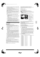
01_EN_3P226891-13Q.fm Page 3 Thursday, December 2, 2010 10:15 AM Note • Be sure to connect an R410A indoor unit. See the catalog for indoor unit models which can be connected. • At above is the total capacity and total number of units of the indoor units when configured in a standard combination. See the technical reference for details on total capacity and total number of indoor units when using a configuration other than the standard combination. The standard combination are as follows.
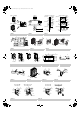
01_EN_3P226891-13Q.fm Page 4 Thursday, December 2, 2010 10:15 AM SELECTION OF LOCATION Select a location for installation that meets the following conditions. Get the customer’s permission. 1. There is no danger of fire due to leakage of inflammable gas. 2. Select the location of the unit in such a way that neither the discharged air nor the sound generated by the unit disturb anyone. 3.
01_EN_3P226891-13Q.fm Page 5 Thursday, December 2, 2010 10:15 AM • For anti-corrosion type use nuts with resin washers. If the paint on nut connections comes off, the anti-corrosion effect may decrease. Resin washers Note Exercise special caution to prevent dirt or dust when passing piping through holes in walls and when passing pipe edges to the exterior. 6-3 Pipe connection • 6.
01_EN_3P226891-13Q.fm Page 6 Thursday, December 2, 2010 10:15 AM 4. Remove the knock hole on the bottom frame and route the piping under the bottom frame. 5. Gas side shutoff valve 6. Liquid side shutoff valve 7. Refrigerant charge port 8. Brazing 9. Liquid side accessory pipe (1) 10. Gas side accessory pipe (1) 11. Gas side accessory pipe (2) 12. Liquid side accessory pipe (2) 13. Knockout hole 14. Punch the knock hole 15. Gas side piping (field supply) 16.
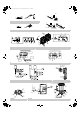
01_EN_3P226891-13Q.fm Page 7 Thursday, December 2, 2010 10:15 AM • Prohibited pattern Front connections to indoor unit Side (bottom) connections Maintain a straight portion of 500 mm or more until the split of the joint without wrapping any onsite piping around this area. Over 500 mm of straight area can be maintained by connecting at least 120 mm of onsite pipe (straight) to the joint. (Refer to figure 18-3) (Refer to figure 18) 1. Warning label 2. Horizontal surface 3. ±15° or less 4. Ground 5.
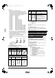
English Between outdoor unit multi connection pipint kit and outdoor unit (Only for multi-connecting systems) Between outdoor unit and indoor unit Between indoor unit and indoor unit Between outdoor unit and outdoor unit Between outdoor unit (*2) and indoor unit Actual Pipe Length Actual Pipe Length Equivalent Length Difference in height Difference in height Difference in height Equivalent Length Total Extension Length Actual Pipe Length Multi-connecting outdoor unit system (Q18~) Individual outdoor
9 Pipe Sizes Selection Part D Part D Part A Part B Outdoor unit Part A Part C Outdoor unit total length (m) of liquid pipe size at φ22.2 total length (m) of liquid pipe size at φ6.4 R= + Q8 type Q10 type Q12 type Q14 type Q16 type Q18~22 type Q24 type Q26~34 type Q36~48 type System name of outdoor unit ×0.022 + ×0.26 + φ19.1 φ15.9 φ12.7 φ9.5 φ22.2 φ19.1 φ15.9 max. size total length (m) of liquid pipe size at φ15.9 standard size liquid pipe 0kg 0.7kg 2.1kg 1.7kg 2.
01_EN_3P226891-13Q.fm Page 10 Thursday, December 2, 2010 10:15 AM 7. FIELD WIRING • Specifications for local wiring are in compliance with IEC60245. • Use wire type H05VV when protected pipes are used. Use wire type H07RN-F when protected pipes are not used. CAUTION • All field wiring and components must be installed by a licensed electrician and must comply with relevant local and national regulations. • Be sure to use a dedicated power circuit. Never use a power supply shared by another appliance.
01_EN_3P226891-13Q.fm Page 11 Thursday, December 2, 2010 10:15 AM Note • Open the knock holes with a hammer or the like. • After knocking out the holes, we recommend you remove any burrs and paint them using the repair paint to prevent rusting. • When passing wiring through the knock holes, remove burrs around the knock holes and protect the wiring with protective tape.
01_EN_3P226891-13Q.fm Page 12 Thursday, December 2, 2010 10:15 AM • When pulling the ground wire out, wire it so that it comes through the cut out section of the cup washer. (See the figure below.) An improper ground connection may prevent a good ground from being achieved. Cup washer 8-1 Preparations Gauge manifold Charge hose valve • To prevent entry of any impurities and insure sufficient pressure resistance, always use the special tools dedicated for R410A.
01_EN_3P226891-13Q.fm Page 13 Thursday, December 2, 2010 10:15 AM Note If moisture might enter the piping, follow belows. (I.e., if doing work during the rainy season, if the actual work takes long enough that condensation may form on the inside of the pipes, if rain might enter the pipes during work, etc.) (1) After performing the vacuum drying for two hours, pressurize to 0.05 MPa (i.e., vacuum breakdown) with nitrogen gas, then depressurize down to –100.
01_EN_3P226891-13Q.fm Page 14 Thursday, December 2, 2010 10:15 AM Shutoff valve size Tightening torque N·m (Turn clockwise to close) Shaft (valve body) φ 9.5 5.4 - 6.6 φ 12.7 8.1 - 9.9 φ 15.9 13.5 - 16.5 Hexagonal wrench 6 mm 27.0 - 33.0 Hexagonal wrench 8 mm φ 19.1 φ 25.4 Hexagonal wrench 4 mm Cap (valve lid) Service port 13.5 - 16.5 18.0 - 22.0 11.5 - 13.9 22.5 - 27.5 [To open] Remove the cap and turn the shaft counterclockwise with the hexagon wrench (JISB4648). 2.
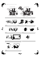
01_EN_3P226891-13Q.fm Page 15 Thursday, December 2, 2010 10:15 AM 11-2 Procedure of Adding Refrigerant charging and check operation WARNING ELECTRIC SHOCK WARNING • Make sure to close the EL. COMPO. BOX lid before turning on the power when performing the refrigerant charging operation. • Perform the setting on the PC-board (A1P) of the outdoor unit and check the LED display after the power is on via the inspection door which is in the EL. COMPO. BOX lid.
01_EN_3P226891-13Q.fm Page 16 Thursday, December 2, 2010 10:15 AM 3. Open the valve C (See the figure 31. The valve A, B and the liquid and gas side shutout valve must be left closed), and charge the refrigerant of the “additional charging amount” from the liquid side shutout valve service port. If the “additional charging amount” was charged fully, close the valve C and go to step 4. If the “additional charging amount” was not charged fully, go to step 4. (Refer to figure 31) 1. Measuring device 2.
01_EN_3P226891-13Q.fm Page 17 Thursday, December 2, 2010 10:15 AM 11-2-1 Refrigerant Charging Operation Procedure [Check operation] Procedures (1) Turn to [Set-up Mode 1] (H1P : light-out) H1P light is usually out. If H1P is l (blinking) or k (lighted-on), press “MODE” button (BS1) once to go into [set-up Mode 1]. (If H2P is lighted-on, check the defect codes with a remote controller to find out the cause. Repair the defect part according to the list on the installation manual (1) 11.
01_EN_3P226891-13Q.fm Page 18 Thursday, December 2, 2010 10:15 AM LED indications h: light-out MODE HWL:i H1P H2P k: light-on l: blnking C/H SELECTOR L.N.O.
01_EN_3P226891-13Q.fm Page 19 Thursday, December 2, 2010 10:15 AM Remote controller indications at check operation (for BRC1C62) A.Before check operation Normal Indications After check operation *1 Regardless of previous settings, it always indicates for cooling operation after a check operation. *2 Indication of “ ” may occasionally blinks, light-on, or lightout, which depends on the setting of cooling/heating switch on the remote controller.
01_EN_3P226891-13Q.fm Page 20 Thursday, December 2, 2010 10:15 AM 12. ONSITE SETTINGS Note In the case of a multi system, all onsite settings should be made on the master unit. Settings made on sub units are invalid. The outdoor unit to which the indoor unit transmission wire are connected is the master unit, and all other units are sub units. 12-1 Onsite Settings With the Power Off If the COOL/HEAT selector was connected to the outdoor unit in Inspection “7.
01_EN_3P226891-13Q.fm Page 21 Thursday, December 2, 2010 10:15 AM 2. 3 Calculate the smallest room volume (m ) Incase like the following, calculate the volume of (A), (B) as a single room or as the smallest room. A.Where there are no smaller room divisions B.Where there is a room division but there is an opening between the rooms sufficiently large to permit a free flow of air back and forth. 1 2 3. 1. opening between rooms 2.
00_CV_3P226891-13Q.