
Service manual

Si06-305 Outdoor Unit
Removal Procedure 127
2. Outdoor Unit
2.1 Removal of External Casing
Procedure Warning Be sure to turn off all power supplies at least 10 min. before disassembling work.
Step Procedure Points
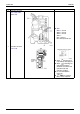
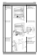
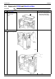
1
The stop valve cover
can be removed when
the fixed screw is
removed.
As three hooks are provided,
slide the cover downward to
remove.
The forced cooling operation
in the pumping down mode
can be carried out by
pushing the operation switch
on the main unit for five
seconds. (The existing
models can do it through the
switch on the PC board just
as well.)
The layout of the connection
ports for the flares has been
changed to horizontal
position from vertical
position.
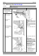
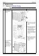
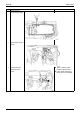
2
The top plate and the
front plate are
constructed in a
monoblock. Remove
the three screws on the
right side and the two
screws on the front
plate.