
Service manual


Checks Si06-305
112 Service Diagnosis
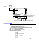
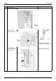
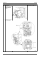
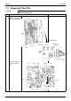
<Measuring positions>
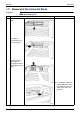
5.1.13 Hall IC Check
Check No.16 1. Check the connector connection.
2. With the power ON, operation OFF, and the connector connected, check the following.
∗
Output voltage of about 5 V between pins 1 and 3.
∗
Generation of 3 pulses between pins 2 and 3 when the fan motor is operating.
Failure of (1)
Æ
faulty PCB
Æ
Replace the PCB.
Failure of (2) Æ
faulty hall IC
Æ
Replace the fan motor.
Both (1) and (2) result
Æ
Replace the PCB.
MULTIMETER
(DC, VOLTAGA RANGE)
DB1
TRM1
S90 THERMISTOR LEAD WIRE S80 FOUR WAY VALVE LEAD WIRE (Heating Pump only)
S70 FAN MOTOR LEAD WIRE
REACTOR LEAD WIRE
COMPRESSOR LEAD WIRE
(R2956)