Si06-305 Service Manual Inverter Pair Floor Standing Type B Series [Applied Models] zInverter Pair : Cooling Only zInverter Pair : Heat Pump
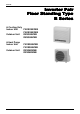
Si06-305 Inverter Pair Floor Standing Type B Series z Cooling Only Indoor Unit FVKS25BVMB FVKS35BVMB Outdoor Unit RKS25BVMB RKS35BVMB z Heat Pump Indoor Unit Outdoor Unit Table of Contents FVXS25BVMB FVXS35BVMB RXS25BVMB RXS35BVMB i
Si06-305 1. Introduction .............................................................................................v 1.1 Safety Cautions ........................................................................................v Part 1 List of Functions ................................................................ 1 1. Functions.................................................................................................2 Part 2 Specifications ......................................................
Si06-305 Part 5 System Configuration....................................................... 43 1. System Configuration............................................................................44 1.1 Operation Instructions ............................................................................44 2. Instruction..............................................................................................45 2.1 2.2 2.3 2.4 2.5 2.6 2.7 2.8 2.9 2.10 2.11 Safety Precautions ..............................
Si06-305 Part 7 Removal Procedure ........................................................ 113 1. Indoor Unit...........................................................................................114 1.1 1.2 1.3 1.4 1.5 1.6 Removal of the Air Filter / Front Panel .................................................114 Removal of the Horizontal Blade..........................................................117 Removal of the Electrical Box ..............................................................
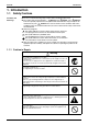
Si06-305 Introduction 1. Introduction 1.1 Safety Cautions Cautions and Warnings Be sure to read the following safety cautions before conducting repair work. The caution items are classified into “ Warning” and “ Caution”. The “ Warning” items are especially important since they can lead to death or serious injury if they are not followed closely. The “ Caution” items can also lead to serious accidents under some conditions if they are not followed.
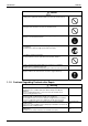
Introduction Si06-305 Caution Do not repair the electrical components with wet hands. Working on the equipment with wet hands can cause an electrical shock. Do not clean the air conditioner by splashing water. Washing the unit with water can cause an electrical shock. Be sure to provide the grounding when repairing the equipment in a humid or wet place, to avoid electrical shocks. Be sure to turn off the power switch and unplug the power cable when cleaning the equipment.
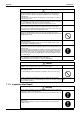
Si06-305 Introduction Warning Be sure to use an exclusive power circuit for the equipment, and follow the technical standards related to the electrical equipment, the internal wiring regulations and the instruction manual for installation when conducting electrical work. Insufficient power circuit capacity and improper electrical work can cause an electrical shock or fire. Be sure to use the specified cable to connect between the indoor and outdoor units.
Introduction Si06-305 Warning Do not use a joined power cable or extension cable, or share the same power outlet with other electrical appliances, since it can cause an electrical shock, excessive heat generation or fire. Caution Check to see if the parts and wires are mounted and connected properly, and if the connections at the soldered or crimped terminals are secure. Improper installation and connections can cause excessive heat generation, fire or an electrical shock.
Si06-305 Part 1 List of Functions 1. Functions.................................................................................................
Functions Si06-305 Operation Limit for Cooling (°C) Basic Function Compressor Operation –15 ~20 PAM Control { { Air Purifying Filter with Bacteriostatic, Virustatic Functions { { Photocatalytic Deodorizing Filter { { Air Purifying Filter with Photocatalytic Deodorizing Function — — Longlife Filter Ultra-Longlife Filter (Option) — — — — Functions –10 –10 ~46 ~46 — Health & Clean Oval Scroll Compressor Swing Compressor — { — { Rotary Compressor Reluctance DC Motor — { — { Mold Pr
Si06-305 Part 2 Specifications 1. Specifications ..........................................................................................4 1.1 Cooling Only.............................................................................................4 1.2 Heat Pump ...............................................................................................
Specifications Si06-305 1. Specifications 1.1 Cooling Only 230V, 50Hz Model Indoor Units Outdoor Units Capacity Rated (Min.~Max.) Moisture Removal Running Current (Rated) Power Consumption Rated (Min.~Max.) Power Factor (Min.~Max.
Si06-305 1.2 Specifications Heat Pump 230V, 50Hz Indoor Units Model FVXS25BVMB RXS25BVMB Outdoor Units Capacity Rated (Min.~Max.) Moisture Removal Running Current (Rated) Power Consumption Rated (Min.~Max.) Power Factor (Min.~Max.
Specifications 6 Si06-305 Specifications
Si06-305 Part 3 Printed Circuit Board Connector Wiring Diagram 1. Printed Circuit Board Connector Wiring Diagram....................................8 1.1 FVKS 25/35 B, FVXS 25/35 B Series.......................................................8 1.2 RKS 25/35 BVMB, RXS 25/35 BVMB ....................................................
Printed Circuit Board Connector Wiring Diagram Si06-305 1. Printed Circuit Board Connector Wiring Diagram 1.
Si06-305 Printed Circuit Board Connector Wiring Diagram Printed Circuit Board (2) (Control PCB) (3) (Display PCB) (4) (Signal Receiver PCB) Printed Circuit Board Connector Wiring Diagram 9
Printed Circuit Board Connector Wiring Diagram 1.
Si06-305 Printed Circuit Board Connector Wiring Diagram Detail of PCB (1) Connect to S11 on PCB (2) 3P100242-1B Detail of PCB (2) Printed Circuit Board Connector Wiring Diagram 11
Printed Circuit Board Connector Wiring Diagram 12 Si06-305 Printed Circuit Board Connector Wiring Diagram
Si06-305 Part 4 Function and Control 1. Main Functions......................................................................................14 1.1 1.2 1.3 1.4 1.5 1.6 1.7 1.8 1.9 1.10 Frequency Principle................................................................................14 Flap Control............................................................................................16 Air Flow Selection...................................................................................
Main Functions Si06-305 1. Main Functions 1.1 Frequency Principle Main Control Parameters Additional Control Parameters Inverter Principle The compressor is frequency-controlled during normal operation.
Si06-305 Inverter Features Main Functions The inverter provides the following features: The regulating capacity can be changed according to the changes in the outdoor air temperature and cooling / heating load. Quick heating and quick cooling The compressor rotational speed is increased when starting the heating (or cooling). This enables a quick set temperature.
Main Functions 1.2 Si06-305 Flap Control Wide-angle Flap The large flaps send a large volume of air all over the room. The flap provides an optimum control in cooling, heating and dry mode. Louvres The louvres, made of elastic synthetic resin, provide a wide range of airflow that guarantees a comfortable air distribution.
Si06-305 1.3 Main Functions Air Flow Selection When setting the air flow selection switch to . Air conditioner automatically decides the appropriate blowing pattern depending on the operating mode / situation. Operating mode Cool mode Situation Blowing pattern When the room has become So that air does not come into direct contact fully cool, or when one hour has with people, air is blown upper air outlet, passed since turning on the air room temperature is equalised. conditioner.
Main Functions 1.4 Si06-305 Fan Speed Control for Indoor Units Control Mode The airflow rate can be automatically controlled depending on the difference between the set temperature and the room temperature. This is done through phase control and Hall IC control. For more information about Hall IC, refer to trouble shooting for fan motor on page 77. Phase Steps Phase control and fan speed control contains 9 steps: LLL, LL, SL, L, ML, M, MH, H and HH.
Si06-305 1.5 Main Functions Programme Dry Function Programme dry function removes humidity while preventing the room temperature from lowering. Since the microcomputer controls both the temperature and air flow volume, the temperature adjustment and fan adjustment buttons are inoperable in this mode. In Case of Inverter Units The microcomputer automatically sets the temperature and fan settings.
Main Functions 1.6 Si06-305 Automatic Operation Automatic Cooling / Heating Function (Heat Pump Only) When the AUTO mode is selected with the remote controller, the microcomputer automatically determines the operation mode from cooling and heating according to the room temperature and setting temperature at the time of the operation startup, and automatically operates in that mode.
Si06-305 1.7 Main Functions Night Set Mode When the OFF timer is set, the Night Set circuit automatically activates. The Night Set circuit maintains the airflow setting made by users. The Night Set Circuit The Night Set circuit continues heating or cooling the room at the set temperature for the first one hour, then automatically lowers the temperature setting slightly in the case of cooling, or raises it slightly in the case of heating, for economical operations.
Main Functions 1.8 Si06-305 Home Leave Operation Outline In order to respond to the customer's need for immediate heating and cooling of the room after returning home or for house care, a measure to switch the temperature and air volume from that for normal time over to outing time by one touch is provided. (This function responds also to the need for keeping up with weak cooling or heating.
Si06-305 1.9 Main Functions Inverter Powerful Operation Outline In order to exploit the cooling and heating capacity to full extent, operate the air conditioner by increasing the indoor fan rotating speed and the compressor frequency. Details of the Control When Powerful button is pushed in each operation mode, the fan speed / setting temperature will be converted to the following states in a period of twenty minutes.
Main Functions Si06-305 1.10 Other Functions 1.10.1 Hot Start Function Heat Pump Only In order to prevent the cold air blast that normally comes when heating is started, the temperature of the heat exchanger of the indoor unit is detected, and either the air flow is stopped or is made very weak thereby carrying out comfortable heating of the room. *The cold air blast is also prevented using a similar control when the defrosting operation is started or when the thermostat gets turned ON. 1.10.
Si06-305 Main Functions 1.10.7 Self-Diagnosis Digital Display The microcomputer continuously monitors main operating conditions of the indoor unit, outdoor unit and the entire system. When an abnormality occur, the LCD remote controller displays error code. These indications allow prompt maintenance operations. 1.10.
Function of Main Structural Parts Si06-305 2. Function of Main Structural Parts 2.
Si06-305 2.2 Function of Main Structural Parts Function of Thermistor 2.2.1 Heat Pump Model A C Four way valve B Compressor (R2827) A Outdoor Heat Exchanger Thermistor (DCB) 1. The outdoor heat exchanger thermistor is used for controlling target discharge temperature. Set a target discharge temperature depending on the outdoor and indoor heat exchanger temperature. Control the electronic expansion valve opening so that the target discharge temperature can be obtained. 2.
Function of Main Structural Parts Si06-305 2.2.2 Cooling Only Model A C B Compressor (R2828) A Outdoor Heat Exchanger Thermistor (DCB) 1. The outdoor heat exchanger thermistor is used for controlling target discharge temperature. Set a target discharge temperature depending on the outdoor and indoor heat exchanger temperature. Control the electronic expansion valve opening so that the target discharge temperature can be obtained. 2.
Si06-305 Control Specification 3. Control Specification 3.1 Mode Hierarchy Outline There are two modes; the mode selected in user’s place (normal air conditioning mode) and forced operation mode for installation and providing service. Detail 1.
Control Specification 3.2 Outline Si06-305 Frequency Control Frequency will be determined according to the difference between room and set temperature. The function is explained as follows. 1. How to determine frequency. 2. Frequency command from an indoor unit. (The difference between a room temperature and the temperature set by the remote controller.) 3. Frequency command from an indoor unit. 4. Frequency initial setting. 5. PI control.
Si06-305 Control Specification 3. Determine lower limit frequency Set a maximum value as an lower limit frequency among the frequency lower limits of the following functions: Pressure difference upkeep. 4. Determine prohibited frequency There is a certain prohibited frequency such as a power supply frequency. Indoor Frequency Command (∆D signal) The difference between a room temperature and the temperature set by the remote controller will be taken as the “∆D signal” and is used for frequency command.
Control Specification 3.3 Si06-305 Controls at Mode Changing / Start-up 3.3.1 Preheating Operation Outline Operate the inverter in the open phase operation with the conditions including the preheating command (only for heat pump model) from the indoor, the outdoor air temperature and discharge pipe temperature. Detail Preheating ON Condition When outdoor air temperature is below 10.5ºC and discharge pipe temperature is below 10.5ºC, inverter in open phase operation starts.
Si06-305 3.4 Control Specification Discharge Pipe Control Outline The discharge pipe temperature is used as the compressor's internal temperature. If the discharge pipe temperature rises above a certain level, the operating frequency upper limit is set to keep this temperature from going up further. Detail Divide the Zone A B A B C D C D 110 103 102 101 (R2836) Management within the Zones Zone Stop zone Drooping zone Unchanged zone Return / Reset zone 3.
Control Specification 3.6 Si06-305 Freeze-up Protection Control Outline During cooling operation, the signals being sent from the indoor unit allow the operating frequency limitation and then prevent freezing of the indoor heat exchanger. (The signal from the indoor unit must be divided into the zones as the followings. Detail Conditions for Start Controlling Judge the controlling start with the indoor heat exchanger temperature after 2 sec from operation start. Control in Each Zone 3.
Si06-305 3.8 Control Specification Fan Control Outline Fan control is carried out according to the following priority. 1. Fan ON control for electric component cooling fan 2. Fan control when defrosting 3. Fan OFF delay when stopped 4. ON/OFF control when cooling operation 5. Tap control when drooping function is working 6. Fan control when forced operation 7. Fan control in low noise mode 8. Fan control during heating operation 9. Fan control in the quiet mode 10.Fan control in the powerful mode 11.
Control Specification Si06-305 3. The set of a constant DOA1CG, DOA2CG, DOA3CG, FCG7 and FCG8 have constants for Cooling / Heating separately and these constants are distinguished with a suffix c/w. Outdoor temperature DOA2CG DOA1CG DOA4CG DOA3CG The lower frequency limit. Cancelled FCG7 FCG8 FCG7 Cancelled (R1044) 4.
Si06-305 Control Specification 3.11 Defrost Control Outline Heat Pump Only Defrosting is carried out by the cooling cycle (reverse cycle). The defrosting time or outdoor heat exchanger temperature must be more than its fixed value when finishing. Detail Conditions for Starting Defrost The starting conditions must be made with the outdoor air temperature and heat exchanger temperature.
Control Specification Si06-305 3.12 Electronic Expansion Valve Control Detail The followings are the examples of control which function in each mode by the electronic expansion valve control. Operation pattern Control for abnormally high discharge pipe temperature The following items are included in the electronic expansion valve control. Electronic expansion valve is fully closed 1. Electronic expansion valve is fully closed when turning on the power. 2. Pressure equalizing control Open Control 1.
Si06-305 Control Specification 3.12.1 Fully Closing with Power ON Initialize the electronic expansion valve when turning on the power, set the opening position and develop pressure equalizing. 3.12.2 Pressure Equalization Control When the compressor is stopped, open and close the electronic expansion valve and develop pressure equalization. 3.12.3 Opening Limit Outline Limit a maximum and minimum opening of the electronic expansion valve.
Control Specification Si06-305 3.12.7 Control when frequency is changed When the target discharge pipe temperature control is active, if the target frequency is changed for a specified value in a certain time period, cancel the target discharge pipe temperature control and change the target opening of the electronic expansion valve according to the shift. 3.12.
Si06-305 Control Specification 3.13 Malfunctions 3.13.1 Sensor Malfunction Detection Sensor malfunction may occur either in the thermistor or current transformer (CT) system. Relating to Thermistor Malfunction 1. Outdoor heat exchanger thermistor 2. Discharge pipe thermistor 3. Fin thermistor 4. Outdoor air thermistor Relating to CT Malfunction When the output frequency is more than 62 Hz and the input current is less than 0.5A, carry out abnormal adjustment. 3.13.
Control Specification Si06-305 3.14 Forced Operation Mode Outline Forced operating mode includes only forced cooling. Detail Forced Cooling Item Forced operation allowing conditions Starting/adjustment Forced Cooling 1) The outdoor unit is not abnormal and not in the 3-minute stand-by mode. 2) The operating mode of the outdoor unit is the stop mode. 3) The forced operation is ON. The forced operation is allowed when the above “and” conditions are met.
Si06-305 Part 5 System Configuration 1. System Configuration............................................................................44 1.1 Operation Instructions ............................................................................44 2. Instruction..............................................................................................45 2.1 2.2 2.3 2.4 2.5 2.6 2.7 2.8 2.9 2.10 2.11 System Configuration Safety Precautions ..................................................................
System Configuration Si06-305 1. System Configuration 1.1 Operation Instructions After the installation and test operation of the room air conditioner have been completed, it should be operated and handled as described below. Every user would like to know the correct method of operation of the room air conditioner, to check if it is capable of cooling (or heating) well, and to know a clever method of using it.
Si06-305 Instruction 2. Instruction 2.1 Safety Precautions Safety precautions • • • • Keep this manual where the operator can easily find them. Read this manual attentively before starting up the unit. For safety reason the operator must read the following cautions carefully. This manual classifies precautions into WARNINGS and CAUTIONS. Be sure to follow all precautions below: they are all important for ensuring safety.
Instruction Si06-305 • Do not stand or sit on the outdoor unit. Do not place any object on the unit to avoid injury, do not remove the fan guard. • Do not place anything under the indoor or outdoor unit that must be kept away from moisture. In certain conditions, moisture in the air may condense and drip. • After a long use, check the unit stand and fittings for damage. • Do not touch the air inlet and alminum fins of outdoor unit. It may cause injury.
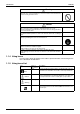
Si06-305 2.2 Instruction Names of Parts Names of parts ■ Indoor Unit 1 2 8 3 10 7 6 ON OFF 2 9 11 4 5 ■ Opening the front grille How to open the grille: (page 22) Air outlet selection switch 12 13 • • This setting blows air from upper outlet only. This setting automatically decides a blow pattern depending on mode and conditions. • This setting is recommended. 14 15 • The unit is shipped from the factory with this setting.
Instruction Si06-305 ■ Outdoor Unit 16 17 18 19 20 ■ Indoor Unit 1. Photocatalytic deodorizing filter and Air purifying filter: • These filters are attached to the inside of the air filters. • The operation mode refers to the following table. 2. Air outlet FVKS FVXS 3. Display 4. Front grille 5. Louvres (vertical blades): (page 12.) • The louvres are inside of the air outlet.
Si06-305 Instruction ■ Remote Controller 1 ON 2 C 5 HOME LEAVE ON/OFF 3 POWERFUL TEMP MODE SILENT FAN 6 4 7 SWING 9 10 CANCEL 14 8 ON 11 15 OFF TIMER 12 13 < ARC433A5, A6 > 1. Signal transmitter: • It sends signals to the indoor unit. 2. Display: • It displays the current settings. (In this illustration, each section is shown with all its displays ON for the purpose of explanation.) 3. HOME LEAVE button: for HOME LEAVE operation (page 16.) 4.
Instruction 2.3 Si06-305 Preparation before Operation Preparation Before Operation ■ To set the batteries 1. Press with a finger and slide the front cover to take it off. Position + and – correctly! 2 – + + 2. Set two dry batteries (AAA). – 3. Set the front cover as before. 3 1 ATTENTION ■ About batteries • When replacing the batteries, use batteries of the same type, and replace the two old batteries together. • When the system is not used for a long time, take the batteries out.
Si06-305 Instruction Preparation Before Operation ■ To operate the remote controller • To use the remote controller, aim the transmitter at the indoor unit. If there is anything to block signals between the unit and the remote controller, such as a curtain, the unit will not operate. • Do not drop the remote controller. Do not get it wet. • The maximum distance for communication is about 7 m. Receiver ■ To fix the remote controller holder on the wall 1.
Instruction Si06-305 ■ To set the clock 1. Press “CLOCK button”. is displayed. C blinks. 2. Press “TIMER setting button” to set the clock to the present time. Holding down “ ” or “ ” button rapidly increases or decreases the time display. HOME LEAVE ON/OFF POWERFUL TEMP MODE SILENT FAN 3. Press “CLOCK button”. blinks. SWING 2 ■ Turn the breaker ON • Turning ON the breaker opens the flap, then closes it again. (This is a normal procedure.) ON CANCEL 1.
Si06-305 2.4 Instruction AUTO·DRY·COOL·HEAT·FAN Operation AUTO · DRY · COOL · HEAT · FAN Operation The air conditioner operates with the operation mode of your choice. From the next time on, the air conditioner will operate with the same operation mode. ■ To start operation C 1. Press “MODE selector button” and select a operation mode. • Each pressing of the button advances the mode setting in sequence.
Instruction Si06-305 ■ To change the air flow rate setting 5. Press “FAN setting button”. DRY mode AUTO or COOL or HEAT or FAN mode Five levels of air flow rate setting from “ plus “ ”“ ” to “ ” ” are available. The air flow rate setting is not variable. • Indoor unit quiet operation When the air flow is set to “ ”, the noise from the indoor unit will become quieter. Use this when making the noise quieter. The unit might lose power when the fan strength is set to a weak level.
Si06-305 2.5 Instruction Adjusting the Air Flow Direction Adjusting the Air Flow Direction You can adjust the air flow direction to increase your comfort. ■ To adjust the horizontal blade (flap) ON C 1. Press “SWING button”. The display will light up and the flaps will begin to swing. 2. When the flaps have reached the desired position, press “SWING button” once more. The display will go blank. The flaps will stop moving.
Instruction Si06-305 ■ Air flow selection • Make air flow selection according to what suits you. When setting the air flow selection switch to . • Air conditioner automatically decides the appropriate blowing pattern depending on the operating mode/situation. Operating mode COOL mode Situation Blowing pattern • When the room has become fully cool, or when one hour has passed since turning on the air conditioner.
Si06-305 2.6 Instruction POWERFUL Operation POWERFUL Operation POWERFUL operation quickly maximizes the cooling (heating) effect in any operation mode. You can get the maximum capacity . ■ To start POWERFUL operation ON 1. Press “POWERFUL button”. • POWERFUL operation ends in 20 minutes. Then the system automatically operates again with the settings which were used before POWERFUL operation. • When using POWERFUL operation, there are some functions which are not available.
Instruction 2.
Si06-305 2.8 Instruction HOME LEAVE Operation HOME LEAVE Operation HOME LEAVE operation is a function which allows you to record your preferred temperature and air flow rate settings. ■ To start HOME LEAVE operation 1. Press “HOME LEAVE button” . • The HOME LEAVE lamp lights up. C ON OFF 1, 2 HOME LEAVE ■ To cancel HOME LEAVE operation 2. Press “HOME LEAVE button” again. • The HOME LEAVE lamp goes off.
Instruction Si06-305 ■ What’s the HOME LEAVE operation Is there a set temperature and air flow rate which is most comfortable, a set temperature and air flow rate which you use the most? HOME LEAVE operation is a function that allows you to record your favorite set temperature and air flow rate. You can start your favorite operation mode simply by pressing the HOME LEAVE button on the remote controller. This function is convenient in the following situations. ■ Useful in these cases. 1.
Si06-305 2.9 Instruction TIMER Operation TIMER Operation Timer functions are useful for automatically switching the air conditioner on or off at night or in the morning. You can also use OFF TIMER and ON TIMER in combination. ■ To use OFF TIMER operation C • Check that the clock is correct. If not, set the clock to the present time. (page 9.) 1. Press “OFF TIMER button”. is displayed. HOME LEAVE ON/OFF POWERFUL TEMP MODE SILENT FAN blinks. 2.
Instruction Si06-305 ■ To use ON TIMER operation • Check that the clock is correct. If not, set the clock to the present time (page 9.). 1. Press “ON TIMER button”. is displayed. C blinks. 2. Press “TIMER Setting button” until the time setting reaches the point you like. • Every pressing of either button increases or decreases the time setting by 10 minutes. Holding down either button changes the setting rapidly. 3. Press “ON TIMER button” again.
Si06-305 Instruction 2.10 Care and Cleaning Care and Cleaning CAUTION Before cleaning, be sure to stop the operation and turn the breaker OFF. Units ■ Indoor unit, Outdoor unit and Remote controller 1. Wipe them with dry soft cloth. ■ Front grille 1. Open the front grille. • Press the two places on the left and right of P U S H the front grille. 2. Remove the front grille. • Remove the chain. • Allowing the grille to fall forward will enable you to remove it. Chain 3.
Instruction Si06-305 Filters 1. Open the front grille. (page 22) 2. Remove the air filter. • Press the claws on the right and left of the air filter down slightly, then pull upward. 3. Take off the air purifying filter, Photocatalytic deodorizing filter. • Hold the tabs of the frame, and remove the claws in 4 places. 4. Clean or replace each filter. See below. 5. Set the air filter, air purifying filter and photocatalytic deodorizing filter as they were and close the front grille.
Si06-305 Instruction Check Check that the base, stand and other fittings of the outdoor unit are not decayed or corroded. Check that nothing blocks the air inlets and the outlets of the indoor unit and the outdoor unit. Check that the earth wire is not disconnected or broken. Check that the drain comes smoothly out of the drain hose during COOL or DRY operation. • If no drain water is seen, water may be leaking from the indoor unit. Stop operation and consult the service shop if this is the case.
Instruction Si06-305 2.11 Trouble Shooting Trouble Shooting These cases are not troubles. The following cases are not air conditioner troubles but have some reasons. You may just continue using it. Case Explanation Operation does not start soon. • When ON/OFF button was pressed soon after operation was stopped. • When the mode was reselected. • This is to protect the air conditioner. You should wait for about 3 minutes. Hot air does not flow out soon after the start of heating operation.
Si06-305 Instruction Check again. Please check again before calling a repair person. Case The air conditioner does not operate. (OPERATION lamp is off) Check 2Hasn’t a breaker turned OFF or a fuse blown? 2Isn’t it a power failure? 2Are batteries set in the remote controller? 2Is the timer setting correct? Cooling (Heating) effect is poor.
Instruction Si06-305 Call the service shop immediately. WARNING ■When an abnormality (such as a burning smell) occurs, stop operation and turn the breaker OFF. Continued operation in an abnormal condition may result in troubles, electric shocks or fire. Consult the service shop where you bought the air conditioner. ■Do not attempt to repair or modify the air conditioner by yourself. Incorrect work may result in electric shocks or fire. Consult the service shop where you bought the air conditioner.
Si06-305 Part 6 Service Diagnosis 1. Caution for Diagnosis............................................................................70 2. Problem Symptoms and Measures .......................................................71 3. Service Check Function ........................................................................72 3.1 ARC433 Series.......................................................................................72 4. Troubleshooting .......................................................
Caution for Diagnosis Si06-305 1. Caution for Diagnosis The Operation lamp flashes when any of the following errors is detected. 1. When a protection device of the indoor or outdoor unit is activated or when the thermistor malfunctions, disabling equipment operation. 2. When a signal transmission error occurs between the indoor and outdoor units. In either case, conduct the diagnostic procedure described in the following sections pages.
Si06-305 Problem Symptoms and Measures 2. Problem Symptoms and Measures Problem Symptom Check Item Details of Measure None of the Units Operates. Check the power supply. Check to make sure that the rated voltage is supplied. Operation Sometimes Stops. Some indoor units do not operate. Equipment operates but does not cool, or does not heat (only for heat pump model). Check the type of the indoor units. Check to make sure that the indoor unit type is compatible with the outdoor unit.
Service Check Function Si06-305 3. Service Check Function 3.1 ARC433 Series In the ARC433A series, the temperature display sections on the main unit indicate corresponding codes. 1. When the timer cancel button is held down for 5 seconds, a “00” indication flashes on the temperature display section. (R2596) 2. Press the timer cancel button repeatedly until a continuous beep is produced. The code indication changes in the sequence shown below, and notifies with along beep.
Si06-305 Troubleshooting 4. Troubleshooting 4.
Troubleshooting 4.2 Si06-305 Indoor Unit PCB Abnormality Remote Controller Display A1 Method of Malfunction Detection Evaluation of zero-cross detection of power supply by indoor unit. Malfunction Decision Conditions When there is no zero-cross detection in approximately 10 continuous seconds. Supposed Causes Faulty indoor unit PCB Faulty connector connection Troubleshooting Caution Be sure to turn off power switch before connect or disconnect connector, or parts damage may be occurred.
Si06-305 4.3 Troubleshooting Freeze-up Protection Control or High Pressure Control Remote Controller Display A5 Method of Malfunction Detection High pressure control (heat pump model only) Malfunction Decision Conditions High pressure control During heating operations, the temperature detected by the indoor heat exchanger thermistor is used for the high pressure control (stop, outdoor fan stop, etc.
Troubleshooting Si06-305 Troubleshooting Caution Check No.6 Refer to P.107 Be sure to turn off power switch before connect or disconnect connector, or parts damage may be occurred. Check the air passage. Is there any short-circuit? YES Provide sufficient air passage. NO Check the intake air filter. Is it very dirty? YES Clean the air filter. NO Check the dust accumulation on the indoor unit heat exchanger. Is it very dirty? YES Clean the heat exchanger. NO Check No.
Si06-305 4.4 Troubleshooting Fan Motor (DC Motor) or Related Abnormality Remote Controller Display A6 Method of Malfunction Detection The rotation speed detected by the hall IC during fan motor operation is used to determine abnormal fan motor operation. Malfunction Decision Conditions When the detected rotation speed is less than 50% of the H tap under maximum fan motor rotation demand.
Troubleshooting Si06-305 Troubleshooting Caution Be sure to turn off power switch before connect or disconnect connector, or parts damage may be occurred. Check No.01 Refer to P.104 Turn off power supply and rotate fan by hand. Check No.02 Refer to P.104 Does fan rotate smoothly? NO Replace fan motor. YES Turn power ON and operate fan. Does it rotate? Turn off power supply NO and disconnect fan motor connector, then turn power ON. YES Check No.
Si06-305 4.5 Troubleshooting Thermistor or Related Abnormality (Indoor Unit) Remote Controller Display C4, C9 Method of Malfunction Detection The temperatures detected by the thermistors are used to determine thermistor errors. Malfunction Decision Conditions When the thermistor input is more than 4.96 V or less than 0.04 V during compressor operation∗. ∗ (reference) When above about 212°C (less than 120 ohms) or below about –50°C (more than 1,860 kohms).
Troubleshooting 4.6 Si06-305 Shutter Drive Motor / Shutter Limit Switch Abnormality Remote Controller Display C7 Method of Malfunction Detection The shutter open/close performance is detected by the limit switch attached on its structure. In this way, the shutter drive motor and the shutter limit switch are checked for failure. Malfunction Decision Conditions When the shutter is open, the limit switch is closed, or vice versa.
Si06-305 4.7 Troubleshooting Signal Transmission Error (between Indoor and Outdoor Units) Remote Controller Display U4 Method of Malfunction Detection The data received from the outdoor unit in indoor unit-outdoor unit signal transmission is checked whether it is normal. Malfunction Decision Conditions When the data sent from the outdoor unit cannot be received normally, or when the content of the data is abnormal. Supposed Causes Faulty outdoor unit PCB. Faulty indoor unit PCB.
Troubleshooting 4.8 Si06-305 OL Activation (Compressor Overload) Remote Controller Display E5 Method of Malfunction Detection A compressor overload is detected through compressor OL. Malfunction Decision Conditions If the compressor OL is activated twice, the system will be shut down. The error counter will reset itself if this or any other error does not occur during the following Supposed Causes 60-minute compressor running time (total time).
Si06-305 4.9 Troubleshooting Compressor Lock Remote Controller Display E6 Method of Malfunction Detection A compressor lock is detected by checking the compressor running condition through the position detection circuit. Malfunction Decision Conditions The system judges the compressor lock, and stops due to over current. The system judges the compressor lock, and cannot operation with position detection within Supposed Causes Compressor locked 15 seconds after start up.
Troubleshooting Si06-305 4.10 Input Over Current Detection Remote Controller Display E8 Method of Malfunction Detection An input over-current is detected by checking the input current value being detected by CT with the compressor running. Malfunction Decision Conditions The following CT input with the compressor running continues for 2.5 seconds.
Si06-305 Troubleshooting 4.11 Four Way Valve Abnormality Remote Controller Display EA Method of Malfunction Detection The indoor air temperature thermistor, the indoor unit heat exchanger thermistor, the outdoor temperature thermistor and the outdoor unit heat exchanger thermistor are checked to see if they function within their normal ranges in the operating mode.
Troubleshooting Si06-305 Troubleshooting Caution Check No.5 Refer to P.106 Check No.6 Refer to P.107 Be sure to turn off power switch before connect or disconnect connector, or parts damage may be occurred. Four way valve coil disconnected (loose)? YES NO YES Harness out of connector? Check No.11 Refer to P.110 Correct. Reconnect. NO Check the continuity of the four way valve coil and harness. Disconnect the harness from the connector. Resistance between harnesses about 3kΩ±0.
Si06-305 Troubleshooting 4.12 Discharge Pipe Temperature Control Remote Controller Display F3 Method of Malfunction Detection The discharge pipe temperature control (stop, frequency drooping, etc.) is checked with the temperature being detected by the discharge pipe thermistor. Malfunction Decision Conditions If a stop takes place 6 times successively due to abnormal discharge pipe temperature, the system will be shut down.
Troubleshooting Si06-305 4.13 Position Sensor Abnormality Remote Controller Display H6 Method of Malfunction Detection A compressor startup failure is detected by checking the compressor running condition through the position detection circuit. Malfunction Decision Conditions The compressor fails to start in about 15 seconds after the compressor run command signal Supposed Causes Compressor relay cable disconnected is sent.
Si06-305 Troubleshooting 4.14 CT or Related Abnormality Remote Controller Display H8 Method of Malfunction Detection A CT or related error is detected by checking the compressor running frequency and CTdetected input current. Malfunction Decision Conditions The compressor running frequency is below 62 Hz and the CT input is below 0.1 V. (The input current is also below 0.5 A.) If this error repeats 4 times, the system will be shut down.
Troubleshooting Si06-305 Troubleshooting Caution Check No.12 Refer to P.111 Be sure to turn off power switch before connect or disconnect connector, or parts damage may be occurred. Turn off the power and turn it on again. Get the system started. ∗ Running current as shown at right with relay cable 1 or 2? YES Current (guideline) NO Check No. 12 Check the capacitor voltage. Rising with increasing frequency 2 sec DC290~380V? Replace the outdoor unit PCB.
Si06-305 Troubleshooting 4.15 Thermistor or Related Abnormality (Outdoor Unit) Remote Controller Display P4, J3, J6, H9 Method of Malfunction Detection This type of error is detected by checking the thermistor input voltage to the microcomputer. [A thermistor error is detected by checking the temperature.] Malfunction Decision Conditions The thermistor input is above 4.96 V or below 0.04 V with the power on.
Troubleshooting Si06-305 Troubleshooting Caution Check No.6 Refer to P.107 Be sure to turn off power switch before connect or disconnect connector, or parts damage may be occurred. Turn on the power again. Error displayed again on remote controller? NO Reconnect. YES Connector or thermistor disconnected? YES Reconnect. NO Check No. 6 Check the thermistor resistance value. NO Normal? YES Check No. 6 Check the indoor unit heat exchanger thermistor resistance value in the heating mode.
Si06-305 Troubleshooting 4.16 Electrical Box Temperature Rise Remote Controller Display L3 Method of Malfunction Detection An electrical box temperature rise is detected by checking the radiation fin thermistor with the compressor off. Malfunction Decision Conditions With the compressor off, the radiation fin temperature is above 122°C. (Reset is made when the temperature drops below 113°C.
Troubleshooting Si06-305 Troubleshooting Caution Check No.6 Refer to P.107 Be sure to turn off power switch before connect or disconnect connector, or parts damage may be occurred. Turn off the power and turn it on again. Check No.7 Refer to P.108 Error again or outdoor unit fan activated? Check No.9 Refer to P.109 WARNING To cool down the electricals, the outdoor unit fan gets started when the radiation fin temperature rises above 120˚C and stops itself when it drops below 113˚C. YES NO Check No.
Si06-305 Troubleshooting 4.17 Radiation Fin Temperature Rise Remote Controller Display L4 Method of Malfunction Detection A radiation fin temperature rise is detected by checking the radiation fin thermistor with the compressor on. Malfunction Decision Conditions Supposed Causes Service Diagnosis If the radiation fin temperature with the compressor on is above 81°C, If a radiation fin temperature rise takes place 4 times successively, the system will be shut down.
Troubleshooting Si06-305 Troubleshooting Check No.6 Refer to P.107 Caution Be sure to turn off power switch before connect or disconnect connector, or parts damage may be occurred. Turn off the power and turn it on again to get the system started. Check No.7 Refer to P.108 Error displayed again? Check No.9 Refer to P.109 YES NO Check No. 6 Check the thermistor resistance value. l Fin thermistor Check the radiation fin temperature.
Si06-305 Troubleshooting 4.18 Output Over Current Detection Remote Controller Display L5 Method of Malfunction Detection An output over-current is detected by checking the current that flows in the inverter DC section. Malfunction Decision Conditions A position signal error occurs while the compressor is running. A speed error occurs while the compressor is running. An output over-current input is fed from the output over-current detection circuit to the microcomputer.
Troubleshooting Si06-305 Troubleshooting Caution Check No.7 Refer to P.108 Be sure to turn off power switch before connect or disconnect connector, or parts damage may be occurred. ∗ An output over-current may result from wrong internal wiring. If the wires have been disconnected and reconnected for part replacement, for example, and the system is interrupted by an output over-current, take the following procedure. NO Stop valve fully open? Check No.8 Refer to P.108 Fully open the stop valve.
Si06-305 Troubleshooting 4.19 Insufficient Gas Remote Controller Display U0 Method of Malfunction Detection Gas shortage detection I : A gas shortage is detected by checking the CT-detected input current value and the compressor running frequency. Gas shortage detection II : A gas shortage is detected by checking the difference between indoor unit heat exchanger temperature and room temperature as well as the difference between outdoor unit heat exchanger temperature and room temperature.
Troubleshooting Si06-305 Troubleshooting Caution Check No.4 Refer to P.105 Check No.6 Refer to P.107 Be sure to turn off power switch before connect or disconnect connector, or parts damage may be occurred. Any thermistor disconnected? NO YES Reconnect in position. * Discharge pipe thermistor * Indoor / outdoor unit heat exchanger thermistor * Room temperature thermistor * Outdoor air thermistor YES Open the stop valve. Stop valve closed? NO Check for gas leakage.
Si06-305 Troubleshooting 4.20 Over-voltage Detection Remote Controller Display U2 Method of Malfunction Detection An abnormal voltage rise is detected by checking the specified over-voltage detection circuit. Malfunction Decision Conditions An over-voltage signal is fed from the over-voltage detection circuit to the microcomputer Supposed Causes Supply voltage not as specified Over-voltage detection circuit defective PAM control part(s) defective (The voltage is over 400V).
Troubleshooting Si06-305 4.21 High Pressure Control in Cooling Remote Controller Display F6 Method of Malfunction Detection High-pressure control (stop, frequency drop, etc.) is activated in the cooling mode if the temperature being sensed by the heat exchanger thermistor exceeds the limit. Malfunction Decision Conditions Activated when the temperature being sensed by the heat exchanger thermistor rises above 60°C. (Deactivated when the said temperature drops below 50°C.
Si06-305 Troubleshooting Troubleshooting Caution Check No.4 Refer to P.105 Check No.6 Refer to P.107 Be sure to turn off power switch before connect or disconnect connector, or parts damage may be occurred. Check the installation space. Check No.7 Installation condition check Abnormal Normal Check No.7 Refer to P.108 Check No.9 Outdoor fan check Abnormal Normal Check No.9 Refer to P.109 Change the air outlet grille position. Change the installation location. Clean the heat exchanger.
Checks Si06-305 5. Checks 5.1 How to Check 5.1.1 Fan Motor Connector Output Check Check No.01 1. 2. 3. 4. 5. Check connector connection. Check motor power supply voltage output (pins 4-7 and 4-8). Check motor control voltage (pins 4-3). Check rotation command voltage output (pins 4-2). Check rotation pulse input (pins 4-1). Upper fan connector 7 6 5 4 3 2 1 Lower fan connector 8 Motor power supply voltage 7 Unused 6 Unused 5 Unused 4 P.
Si06-305 Checks 5.1.3 Electronic Expansion Valve Check Check No.4 Conduct the followings to check the electronic expansion valve (EV). 1. Check to see if the EV connector is correctly inserted in the PCB. Compare the EV unit and the connector number. 2. Turn the power off and back on again, and check to see if all the EVs generate latching sound. 3. If any of the EVs does not generate latching noise in the above step 2, disconnect that connector and check the conductivity using a tester.
Checks Si06-305 5.1.4 Four Way Valve Performance Check Check No.5 Turn off the power and turn it on again. Start the heating-mode run. S80 voltage at DC 180-220 V with compressor on? (Fig. 1) ∗ Four way valve coil Cooling / dry : No continuity Heating : Continuity NO Replace the outdoor unit PCB. YES Disconnect the four way valve coil from the connector and check the continuity. Four way valve coil resistance at 3kΩ±0.5kΩ? NO YES Replace the four way valve coil. Replace the four way valve.
Si06-305 Checks 5.1.5 Thermistor Resistance Check Check No.6 Remove the connectors of the thermistors on the PCB, and measure the resistance of each thermistor using tester. The relationship between normal temperature and resistance is shown in the graph and the table below. Thermistor R25°C=20kΩ B=3950 Service Diagnosis Temperature (°C) -20 211.0 (kΩ) -15 -10 150 116.5 -5 0 88 67.2 5 10 51.9 40 15 20 31.8 25 25 30 20 16 35 40 13 10.6 45 50 8.7 7.
Checks Si06-305 5.1.6 Installation Condition Check Check No.7 Installation condition check Check the allowable dimensions of the air suction and discharge area. Normal Does the discharged air from other outdoor unit cause an increase of the suction air temperature? Abnormal YES Change the position of the air discharge grille or the installation location. Change the position of the air discharge grille or the installation location.
Si06-305 Checks 5.1.8 Outdoor Unit Fan System Check (With AC Motor) Check No.9 Check the outdoor fan system. Does the outdoor fan rotate? NO YES Does the outdoor unit fan start just after the power is turned on? NO Abnormal Check the fan motor lead wire Repair. connector for secure connection. Normal YES Are the resistance at connector leads ∞? 1. red - black, 2. white - black YES Replace the fan motor. NO Continuity Check the fan Replace the fan motor. capacitor for continuity.
Checks Si06-305 5.1.9 Power Supply Waveforms Check Check No.10 Measure the power supply waveform between pins 1 and 3 on the terminal board, and check the waveform disturbance. Check to see if the power supply waveform is a sine wave (Fig.1). Check to see if there is waveform disturbance near the zero cross (sections circled in Fig.2) [Fig.1] [Fig.2] 5.1.10 Inverter Units Refrigerant System Check Check No.
Si06-305 Checks 5.1.11 Capacitor Voltage Check Check No.12 < Measuring method > Before measuring, operate the unit for several minutes, then shut down the operation by force using the circuit breaker. If the unit is shut down using the remote controller instead of the circuit breaker, the capacitor discharges the electric load, thus disallowing accurate measurement. Note: The charge section is applied with high voltage. Therefore, exercise caution during measurement to prevent electric shock.
Checks Si06-305 MULTIMETER (DC, VOLTAGA RANGE) DB1 TRM1 S90 THERMISTOR LEAD WIRE S80 FOUR WAY VALVE LEAD WIRE (Heating Pump only) S70 FAN MOTOR LEAD WIRE COMPRESSOR LEAD WIRE REACTOR LEAD WIRE (R2956) 5.1.13 Hall IC Check Check No.16 1. Check the connector connection. 2. With the power ON, operation OFF, and the connector connected, check the following. ∗Output voltage of about 5 V between pins 1 and 3.
Si06-305 Part 7 Removal Procedure 1. Indoor Unit...........................................................................................114 1.1 1.2 1.3 1.4 1.5 1.6 Removal of the Air Filter / Front Panel .................................................114 Removal of the Horizontal Blade..........................................................117 Removal of the Electrical Box ..............................................................118 Removal of the PCB...........................................
Indoor Unit Si06-305 1. Indoor Unit 1.1 Removal of the Air Filter / Front Panel Procedure Warning Be sure to wait 10 minutes or more after turning off all power supplies before disassembling work. Step 1 Appearance Procedure Points Operation panel Enlarged illustration shows operation panel section. 2 114 Remove the front panel from the unit. Push on the left and right upper parts of the panel marked with “PUSH” to open the front panel.
Si06-305 Step Indoor Unit Procedure 3 Press down the two hooks located at left and right side upper parts of the air filter, then bend slightly the air filter to remove it. 4 Unhook the chain.
Indoor Unit Step Si06-305 Procedure 5 Disengage the three hooks on the bottom of the front panel. 6 Remove the four screws to take out the front grille.
Si06-305 1.2 Indoor Unit Removal of the Horizontal Blade Procedure Warning Be sure to wait 10 minutes or more after turning off all power supplies before disassembling work Step 1 Open the horizontal Procedure Points blade. 2 Disengage the supporting bracket at the center position. 3 Bend the horizontal blade slightly to disengage the shafts at left and right side of the blade.
Indoor Unit 1.3 Si06-305 Removal of the Electrical Box Procedure Warning Be sure to wait 10 minutes or more after turning off all power supplies before disassembling work Step 1 Set the horizontal Procedure Points blade in horizontal position to take out the front grille forward. 2 Remove the setting screw to remove the wire clamp. 3 Disconnect the four connectors of the lead wire.
Si06-305 Step Indoor Unit Procedure 4 Remove the room temperature thermistor. 5 Remove the heat exchanger thermistor. Points Be sure not to drop the thermistor retaining spring 6 Dismount the two screws to remove the drip proof plate.
Indoor Unit Step Procedure 7 To remove the electrical box, dismount the two fixing screws and pull out the box forward. 8 Illustration shows parts in the electrical box.
Si06-305 1.4 Indoor Unit Removal of the PCB Procedure Warning Be sure to wait 10 minutes or more after turning off all power supplies before disassembling work Step 1 Dismount the fixing Procedure Points screw to remove PCBs from the electrical box. Display PCB 2 Illustration shows the control PCB (indoor unit).
Indoor Unit Step 3 Si06-305 Procedure Points Illustration shows the power supply PCB (indoor unit). SW2 SW2-1 : unused SW2-2 : unused SW2-3 : unused SW2-4 : OFF - initial set ON - limit upward air flow 4 Illustration shows the service PCB. Select to discharge air only from top discharge port. to discharge air Select with automatic pattern decided in accordance with operation mode and operation conditions. It is recommendable to select . has been selected before factory shipment.
Si06-305 1.5 Indoor Unit Removal of the Heat Exchanger Procedure Warning Be sure to wait 10 minutes or more after turning off all power supplies before disassembling work Step Procedure Conduct pump-down Points Mounting screw M4 × 16 operation and check that gas has been purged completely before starting service work. 1 Dismount the two screws to remove the top discharge grille. 2 3 4 Remove the heat exchanger. Disconnect the flared joint of liquid pipe using two wrenches.
Indoor Unit Step Si06-305 Procedure Points 5 Dismount the fixing screw to remove the pipe retaining plate of the heat exchanger. Push the pipe retaining plate backward to disengage hook, then open the retaining plate using straight edge of screw-driver to remove the plate. Mounting screw M4 × 16 6 Remove the two screws located at left side of the heat exchanger.
Si06-305 1.6 Indoor Unit Removal of the Fan Rotor / Fan Motor Procedure Warning Be sure to wait 10 minutes or more after turning off all power supplies before disassembling work Step 1 For removal of the drain pan, disconnect the drain hose, then dismount the two screws located at left and right sides. Procedure Points Be careful not to wet the floor with drain water. Disengage harness for drain pan from right side hook. 2 Remove the drain pan.
Indoor Unit Step 4 5 6 126 Si06-305 Procedure Points Dismount the six screws (three for the upper side motor and three for the bottom one) to remove the fan motors. Short lead wire: for the upper Remove the motors and cross flow fans. Loosen the fixing screw to To remove the casing, dismount the four screws at front side and the other four screws at rear side. Casing mounting screw fan motor Long lead wire: for the bottom fan motor Mounting screw M4 × 16 separate the fan and motor.
Si06-305 Outdoor Unit 2. Outdoor Unit 2.1 Removal of External Casing Procedure Step 1 The stop valve cover Warning Be sure to turn off all power supplies at least 10 min. before disassembling work. Procedure Points can be removed when the fixed screw is removed. As three hooks are provided, slide the cover downward to remove. The forced cooling operation in the pumping down mode can be carried out by pushing the operation switch on the main unit for five seconds.
Outdoor Unit Step Si06-305 Procedure Points 3 Remove the three screws on the left side. 4 Remove the one fixed screw in the rear of the top plate. Once lift the top plate and then remove it forward. The left side plate and the The front plate and the left side plate can be removed when the one fixed screw is removed. Sectional view at the front. 5 bellmouth can be removed all at once. When restoring the top plate, move it horizontally and get it down for the easy work.
Si06-305 2.2 Outdoor Unit Removal of Bellmouth and Left Side Plate Procedure Step 1 The bellmouth is attached to the front plate with two screws and four hooks. 2 Remove the two screws and undo the four hooks to release the bellmouth. Removal Procedure Warning Be sure to turn off all power supplies at least 10 min. before disassembling work. Procedure Points Remove the bellmouth from the front plate after removing the two screws which are set below.
Outdoor Unit 2.3 Si06-305 Removal of PCB and Electrical Box Procedure Step 1. Remove the shelter. 1 Undo the five hooks and remove the shelter. Warning Be sure to turn off all power supplies at least 10 min. before disassembling work. Procedure Points The shelter has five hooks. Be sure to avoid forgetting to restore the shelter and to avoid losing or damaging it. 2. Remove the PCB. 1 Disconnect the ground wire.
Si06-305 Step Outdoor Unit Procedure 2 Remove the four screws fixing the PCB. 3 Disconnect the six wire harness. 4 Disconnect the two connectors of the reactor. Points There is another reactor located on bottom frame. Fasten clamp materials as before when re-assembling.
Outdoor Unit Step Procedure 5 Undo the eight hooks and the PCB can be disengaged. 6 Disconnect the three wires from the PCB. 132 Si06-305 Points The PCB has eight hooks.
Si06-305 Step 7 Outdoor Unit Procedure Points The PCB can completely be released. 3. Remove the electrical box. 1 Remove the two screws fixing the electrical box.
Outdoor Unit Step 2 Si06-305 Procedure Points Lift and remove the electrical box. 4. Remove the molded interconnect device (MID). 1 Remove the one screw fixing the MID.
Si06-305 Step 2 Outdoor Unit Procedure Points Slide the MID upward and release.
Outdoor Unit 2.4 Removal of Propeller Fan and Fan Motor Procedure Step connector S70. 1 Release the lead-wires of the fan motor from the groove of the switch box. 3 136 Warning Be sure to turn off all power supplies at least 10 min. before disassembling work. Procedure Disconnect the fan motor 2 Si06-305 The propeller fan can be removed when the washer faced nut (M8) is removed. Points Remove the external plates and the drip proof cover protecting the electric parts.
Si06-305 Step 4 Outdoor Unit Procedure Points Remove the fan motor.
Outdoor Unit 2.5 Si06-305 Removal of Compressor Noise Absorption Pad Procedure Step Warning Be sure to turn off all power supplies at least 10 min. before disassembling work. Procedure Points 1. Remove the right side plate. 1 Remove the three screws for removing the right side plate. 2 Lift the right side plate to disengage the hooks. 2. Remove the noise absorber. 1 Untie the string fixing the noise absorption pad for the body to the compressor. 138 Insert the three hooks for the restoration.
Si06-305 Step Outdoor Unit Procedure Points 2 Pull out the noise absorption pad for the body. 3 Pull out the top pad of the noise absorption (a). Since the slit prepared for Pull out the noise absorption pad (b). When restoring, the noise 4 Removal Procedure the piping on the noise absorption pad is torn easily, remove the pad carefully. absorption pad should pass the internal side of the piping.
Outdoor Unit 2.6 Removal of Partition Plate and Reactor Procedure Step 1. Remove the partition plate. 1 Remove the two screws fixing the partition plate. 2 Pull the partition plate upward to remove. 140 Si06-305 Warning Be sure to turn off all power supplies at least 10 min. before disassembling work.
Si06-305 Step 3 Outdoor Unit Procedure Points When restoring the partition plate, fit the hook into the bottom frame. 2. Remove the reactor. 1 The reactor can be released by removing the fixed screw. 3. Remove the reactor assembly. 1 Remove the one screw fixing the reactor assembly to the bottom frame.
Outdoor Unit Step 2 142 Si06-305 Procedure Points Slide the reactor assembly this side and release.
Si06-305 2.7 Outdoor Unit Removal of Four Way Valve and Motor Valve Procedure Step Warning Be sure to turn off all power supplies at least 10 min. before disassembling work. Procedure Points 1. Remove the parts around the four way valve. 1 Remove the terminal cover and the lead wires of the compressor so as not to be burnt out by a gas brazing machine. 2 Remove the thermistor for the heat exchanger. The thermistor for the heat exchanger is fixed by a clamp material at one portion.
Outdoor Unit Step 4 Si06-305 Procedure Points Remove the motor valve coil. Confirm that the refrigerant is completely empty in the refrigerant circuit before starting work. 5 Provide a protective sheet or a steel plate so that the brazing flame can’t influence the circumstance around the four way valve. 6 Heat up the four portions of brazing parts on the four way valve. Remove the four way valve (a), (b), (c), (d).
Si06-305 Step 7 8 Outdoor Unit Procedure Heat up the brazing parts and withdraw the pipes connected to the four way valve by pliers and so on. Heat up the two portions of brazing parts on the motor valve and remove. Points In case that the removal seems to be hard; 1. Remove the piping connection part (brazing part) which is easy to remove and restore. 2. Cut the pipes on the main unit by a miniature copper tube cutter in order to make it easy to remove.
Outdoor Unit 2.8 Removal of Compressor Procedure Step 1. Remove the parts around the compressor. 1 Remove the terminal cover and the lead wires of the compressor so as not to be burnt out by a gas brazing machine. 146 Si06-305 Warning Be sure to turn off all power supplies at least 10 min. before disassembling work. Procedure Points Be careful so as not to burn the compressor terminals or the name plate.
Si06-305 Step 2 3 Outdoor Unit Procedure The mounting nut for the compressor is only one piece. Remove the nut by an open-end wrench. Removal Procedure Points Remove the four way valve and the motor valve also so as not to be burnt out.
Outdoor Unit Step Si06-305 Procedure Points Confirm that the refrigerant is completely empty in the refrigerant circuit before starting work. Be sure to apply nitrogen’s replacement when heating up the brazing part. 1 Remove the brazing part on the discharge side of the compressor. 2 Heat up the brazing part on the suction side of the compressor and then remove it. 3 Lift the compressor and remove it.
Si06-305 Part 8 Appendix 1. Piping Diagrams..................................................................................150 1.1 Indoor Units ..........................................................................................150 1.2 Outdoor Units .......................................................................................151 2. Wiring Diagrams..................................................................................153 2.1 Indoor Units ........................................
Piping Diagrams Si06-305 1. Piping Diagrams 1.1 Indoor Units FVKS25BVMB, FVKS35BVMB, FVXS25BVMB, FVXS35BVMB INDOOR UNIT HEAT EXCHANGER 7.9CuT M CROSS FLOW FAN FAN MOTOR THERMISTOR ON HEAT EXCH. M CROSS FLOW FAN FAN MOTOR 7.0CuT 7.0CuT FIELD PIPING (6.4CuT) SINGLE UNION JOINT 9.5CuT FIELD PIPING (9.
Si06-305 1.2 Piping Diagrams Outdoor Units RKS25BVMB OUTDOOR UNIT OUTDOOR TEMPERETURE THERMISTOR HEAT EXCHANGER 7.9CuT 7.9CuT MOTOR OPERATED VALVE 6.4CuT 6.4CuT 6.4CuT HEAT EXCHANGER THERMISTOR CAPILLARY TUBE 1 7.9CuT MUFFLER WITH FILTER CAPILLARY TUBE 2 M MUFFLER WITH FILTER 6.4CuT 7.9CuT PROPELLER FAN MUFFLER WITH FILTER 6.4CuT LIQUID STOP VALVE MUFFLER DISCHARGE PIPE THERMISTOR 7.9CuT 9.5CuT COMPRESSOR FIELD PIPING 9.5CuT ACCUMLATOR MUFFLER FIELD PIPING (6.
Piping Diagrams Si06-305 RXS25BVMB OUTDOOR UNIT 7.9CuT OUTDOOR TEMPERATURE THERMISTOR HEAT EXCHANGER 7.9CuT HEAT EXCHANGER THERMISTOR CAPILLARY TUBE 1 7.9CuT 6.4CuT MUFFLER WITH FILTER CAPILLARY TUBE 2 M FILTER 6.4CuT MOTOR OPERATED VALVE 6.4CuT LIQUID RECEIVER WITH FILTER 6.4CuT 9.5CuT PROPELLER FAN 9.5CuT 7.9CuT MUFFLER WITH FILTER FOUR WAY VALVE ON: COOLING 6.4CuT LIQUID STOP VALVE MUFFLER DISCHARGE PIPE THERMISTOR 9.5CuT 9.
Si06-305 Wiring Diagrams 2. Wiring Diagrams 2.1 Indoor Units FVKS25BVMB, FVKS35BVMB, FVXS25BVMB, FVXS35BVMB PCB3 S26 S2W(4) S4W TRANSMISSION CIRCUIT PCB2 WIRELESS REMOTE CONTROLLER 3.15A H1 FU H2 S25 BLK WHT RED GRN/ YLW H3 S8 S201 S202 S203 S204 S301 S43 PCB1 FG S23 H1P H2P H3P S1W SIGNAL RECEIVER S6 M1S S21 HA M S41 M2S M L1S indoor S302 S31 S32 outdoor FIELD WIRING.
Wiring Diagrams 2.2 Si06-305 Outdoor Units RKS25BVMB, RKS35BVMB –Cooling Only– t˚ FIELD WIRING. BLK WHT PCB1 S HN1 PCB2 HL2 L1 FU2 HL1 20A HN2 V2 SA1 V3 E 1 7 BLK BLK ORG HR4 HN3 BLU MRM10 FU1 3.
Si06-305 Index Numerics 00 ...........................................................................73 3 Minutes Stand-by ................................................32 A A1 ...........................................................................74 A5 ...........................................................................75 A6 ...........................................................................77 Air Filter ................................................................
Si06-305 J J3 ...........................................................................91 J6 ...........................................................................91 L L3 ...........................................................................93 L4 ...........................................................................95 L5 ...........................................................................97 LED11 ......................................................................8 LED12 ........
Si06-305 U2 .........................................................................101 U4 ...........................................................................81 V V1 .............................................................................8 Voltage Detection Function ....................................42 W Wiring Diagrams ...................................................
Si06-305 iv Index
Si06-305 Drawings & Flow Charts A Inverter Powerful Operation .................................. 23 Inverter Units Refrigerant System Check ............ 110 ARC433A series ....................................................72 Automatic Air Flow Control for Cooling ..................18 Automatic Air Flow Control for Heating ..................18 Automatic Operation ..............................................20 Auto-swing .............................................................
Si06-305 W Wiring Diagrams Indoor Units ...................................................153 Outdoor Units ................................................
Head office: Umeda Center Bldg., 4-12, Nakazaki-Nishi 2-chome, Kita-ku, Osaka, 530-8323 Japan Zandvoordestraat 300, B-8400 Oostende, Belgium Tokyo office: Shinjuku Sumitomo Bldg., 6-1 Nishi-Shinjuku 2-chome, Shinjuku-ku, Tokyo, 163-0235 Japan z For further improvement, specifications or designs are subject to change without prior notice.