INSTALLATION MANUAL R410A Split Series Installation manual R410A Split series English Manuel d’installation Français Série split R410A Manual de instalación Español Serie Split R410A Models RXN15KEVJU RKN15KEVJU RXN18KEVJU RKN18KEVJU RXN24KEVJU RKN24KEVJU 00_CV_3P273470-2.
Safety Precautions • Read these Safety Precautions carefully to ensure correct installation. • This manual classifies the precautions into DANGER, WARNING and CAUTION. Be sure to follow all the precautions below: they are all important for ensuring safety. DANGER ......Indicates an imminently hazardous situation which, if not avoided, will result in death or serious injury. WARNING ....Failure to follow any of WARNING is likely to result in such grave consequences as death or serious injury. CAUTION .....
Safety Precautions WARNING • After connecting all wires be sure to shape the cables so that they do not put undue stress on the electrical covers, panels or terminals. Install covers over the wires. Incomplete cover installation may cause terminal overheating, electrical shock, fire or equipment damage. • When installing or relocating the system, be sure to keep the refrigerant circuit free from all substances other than the specified refrigerant (R410A), such as air.
Precautions for Selecting the Location 1) Choose a place solid enough to bear the weight and vibration of the unit, where the operation noise will not be amplified. 2) Choose a location where the hot air discharged from the unit or the operation noise will not cause a nuisance to the neighbors of the user. 3) Avoid places near a bedroom and the like, so that the operation noise will cause no trouble. 4) There must be sufficient spaces for carrying the unit into and out of the site.
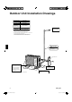
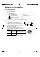
Outdoor Unit Installation Drawings Max. allowable length 98.4ft (30m) ** Min. allowable length 4.92ft (1.5m) Max. allowable height 65.6ft (20m) * Additional refrigerant required for refrigerant pipe exceeding 32.8ft (10m) in length. 0.21oz/ft (20g/m) Gas pipe O.D. 1/2 inch (12.7mm) Liquid pipe O.D. 1/4 inch (6.4mm) Wrap the insulation pipe with the finishing tape from bottom to top. * Be sure to add the proper amount of additional refrigerant.
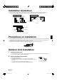
Installation Guidelines • Where a wall or other obstacle is in the path of outdoor unit’s inlet or outlet airflow, follow the installation guidelines below. • For any of the below installation patterns, the wall height on the outlet side should be 47-1/4 inch (1200mm) or less.
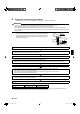
Outdoor Unit Installation 3. Flaring the pipe end 1) Cut the pipe end with a pipe cutter. 2) Remove burrs with the cut surface facing downward so that the chips do not enter the pipe. 3) Put the flare nut on the pipe. 4) Flare the pipe. 5) Check that the flaring is properly made. (Cut exactly at right angles.) Remove burrs. Flaring Set exactly at the position shown below. A Die A Flare tool for R410A Conventional flare tool Clutch-type Clutch-type (Rigid-type) Wing-nut type (Imperial-type) 0-0.
5. Purging air and checking gas leakage • When piping work is completed, it is necessary to purge the air and check for gas leakage. WARNING • • • • Do not mix any substance other than the specified refrigerant (R410A) into the refrigeration cycle. When refrigerant gas leaks occur, ventilate the room as soon and as much as possible. R410A, as well as other refrigerants, should always be recovered and never be released directly into the environment. Use a vacuum pump for R410A exclusively.
Outdoor Unit Installation 6. Refilling the refrigerant Check the type of refrigerant to be used on the machine nameplate. Precautions when adding R410A Fill from the liquid pipe in liquid form. It is a mixed refrigerant, so adding it in gas form may cause the refrigerant composition to change, preventing normal operation. 1) Before filling, check whether the cylinder has a siphon attached or not. (It should have something like “liquid filling siphon attached” displayed on it.
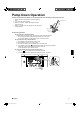
Pump Down Operation In order to protect the environment, be sure to pump down when relocating or disposing of the unit. 1) Remove the valve cap from liquid stop valve and gas stop valve. 2) Carry out forced cooling operation. 3) After 5 to 10 minutes, close the liquid stop valve with a hexagonal wrench. 4) After 2 to 3 minutes, close the gas stop valve and stop forced cooling operation.
Wiring WARNING • Do not use tapped wires, stranded wires, extension cords, or starburst connections, as they may cause overheating, electrical shock, or fire. • Do not use locally purchased electrical parts inside the product. (Do not branch the power for the drain pump, etc., from the terminal block.) Doing so may cause electric shock or fire. • Be sure to install a ground fault circuit interrupter breaker. (One that can handle higher harmonics.
CAUTION • When connecting the connection wires to the terminal board using a single core wire, be sure to perform curling. Problems with the work may cause heat and fires. Strip wire end to this point. Good Excessive strip length may cause electrical shock or leakage. Wrong Stripping wire at terminal block 3) Pull the wire and make sure that it does not disconnect. Then fix the wire in place with a wire stop.
Trial Operation and Testing 1. Trial operation and testing 1-1 Measure the supply voltage and make sure that it falls in the specified range. 1-2 Trial operation should be carried out in either cooling or heating mode. For heat pump • In cooling mode, select the lowest programmable temperature; in heating mode, select the highest programmable temperature. 1) Trial operation may be disabled in either mode depending on the room temperature.
Two-dimensional bar code is a code for manufacturing. 3P273470-2 00_CV_3P273470-2.