
User`s manual

3 English
• Do not place the controller exposed to direct sunlight.
The LCD display may get discolored, failing to display the
data.
• Avoid placing the controller in a spot splashed with
water.
Water coming inside the controller may cause an electric
leak or may damage the internal electronic parts.
• Never pull or twist the electric wire of a remote control-
ler.
It may cause the unit to malfunction.
WARNING
(For moving and reinstalling/
repairing)
• Do not modify the unit.
This may cause electric shock or fire.
• Ask your dealer to move and reinstall the unit.
Incomplete installation may result in a water leakage, elec-
tric shock, and fire.
• Do not disassemble or repair the unit yourself.
This may cause electric shock or fire.
Contact your dealer to have such work done.
• When removing the unit, be sure not to tip it.
The water inside the unit may drip or leak out, and get on
furniture, etc.
2. WHAT TO DO BEFORE OPERATION
This operation manual is for the following systems with stan-
dard control. Before initiating operation, contact your Daikin
dealer for the operation that corresponds to your system type
and mark.
If your installation has a customized control system, ask your
dealer for the operation that corresponds to your system.
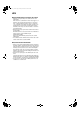
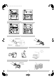
2-1 NAMES OF PARTS (Refer to figure 1)
(1) Hanger bracket
(2) Duct connecting flange
(3) Exhaust fan
(4) Air filter (Long life filter)
(5) Damper
(6) Electric parts box
(7) Maintenance cover
(8) Heat exchanger elements
(9) Name plate
(10) Air supply fan
(11) Direct expansion coil
(12) Gas pipe
(13) Liquid pipe
(14) Drain outlet
(15) Humidifier (Natural evaporating type)
(16) Strainer (included)
(17) Feed water tank
(18) Solenoid valve
(19) Remote controller (Optional accessory)
(20) Damper motor
(21) EA Exhaust air to outdoors
(22) OA Fresh air from outdoors
(23) RA Return air from room
(24) SA Supply air to room
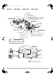
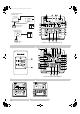
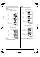
2-2 REMOTE CONTROLLER AND CHANGEOVER
SWITCH: NAME AND FUNCTION OF EACH
SWITCH AND DISPLAY
(Refer to figure 3 and 4)
• Only the items marked with an asterisk (∗ mark) are expla-
nation relating to the functions and display of the unit.
Unmarked items are functions of the combined air condition-
ers. When using buttons for functions which are not avail-
able (buttons which are not described in the text) will cause
“NOT AVAILABLE” to be displayed.
Contact your dealer for more detailed descriptions of those
functions (buttons).
∗1 On/off button
Press the button and the system will start. Press the button
again and the system will stop.
∗2 Operation lamp (red)
The lamp lights up during operation.
∗3 Display “ ” (changeover under control)
May be displayed when combined with a VRV-system air
conditioner.
It is impossible to changeover heat/cool with the remote
controller when this icon is displayed.
4Display
“”
(air flow flap)
This displays the direction and mode of the air flow flap of
the combined air conditioner.
5 Display “ ” (ventilation/air cleaning)
This display shows that the total heat exchange and the air
cleaning unit are in operation. (these are optional accesso-
ries)
6Display
“”
(set temperature)
This displays the set temperature of the combined air con-
ditioner.
It is not displayed when the unit is used as an independent
system.
7Display
“”
“”
“”
“”
“”
(operation
mode)
This displays the operating status of the combined air con-
ditioner.
• There is no “heating” for the VRVII system (Cooling only
type).
• “ ” is only available for systems operating in cooling
and heating at the same time.
∗8Display
“”
(programmed time)
This display shows the programmed time of the system
start or stop.
9Display
“”
(inspection/test operation)
When the inspection/test operation button is pressed, the
display shows the mode in which the system actually is.
•
Do not use under usual use (service person/installer only).
10 Display “ ” (under centralized control)
When this display shows, the system is under centralized
control. (This is not a standard specification.)
∗11 Display
“”
(fan speed)
This display shows the fan speed you have selected.
∗ This is only displayed when the fan speed selection but-
ton is pressed. It normally displays the set fan strength of
the combined air conditioner.
∗12 Display
“”
(time to clean air filter)
Refer to “4-1 HOW TO CLEAN THE AIR FILTER”.
13 Display
“”
(defrost/hot start)
It may be displayed when the combined air conditioner is in
heating mode.
C
TEST
3P130767-1_En.fm Page 3 Wednesday, December 17, 2003 7:39 PM