3P130767-1_Cover.
3P130767-1_illust.fm Page 0 Friday, December 12, 2003 9:26 AM HRV HRV; Ventilazione per recupero del calore • Grazie di aver acquistato questo scambiatore di calore totale Daikin. Prima di usare lo scambiatore di calore totale, leggere con attenzione questo manuale d’istruzioni. Esso insegna il modo corretto di utilizzare l’unità e fornisce consigli, nel caso si verifichino dei problemi. Il manuale si riferisce solo all’unità interna. Usarlo insieme al manuale di istruzioni dell’unità esterna.
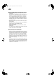
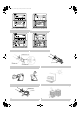
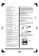
P130767-1_illust.fm Page 1 Friday, December 12, 2003 9:26 AM MODELS VKMP50GMR VKMP80GMR VKMP100GMR (1) Hanger bracket (7) Maintenance cover (8) Heat exchanger elements (3) Exhaust fan It exchanges the heat (temperature and humidity) from indoors with the air taken in from outdoors, changes the outside air to the same condition as indoors and then brings it indoors.
3P130767-1_illust.
3P130767-1_illust.
3P130767-1_En.fm Page 1 Wednesday, December 17, 2003 7:39 PM With DX coil & Humidifer VKMP50GMR VKMP80GMR VKMP100GMR Total Heat Exchanger HRV (Heat Reclaim Ventilation) -with DX Coil- CONTENTS 1. 2. 3. 4. 5. 1. ILLUSTRATIONS................................................... [1][2][3] SAFETY CAUTIONS ....................................................... 1 WHAT TO DO BEFORE OPERATION............................. 3 OPERATION PROCEDURE............................................
3P130767-1_En.fm Page 2 Wednesday, December 17, 2003 7:39 PM • Never press the button of the remote controller with a hard, pointed object. The remote controller may be damaged. • Do not let any kind of sprays get on the remote controller (insecticides, cleaning materials, etc.) This may cause breakage, deformation, or malfunction. • Do not wipe the controller operation panel with benzine, thinner, chemical dustcloth, etc. The panel may get discolored or the coating peeled off.
3P130767-1_En.fm Page 3 Wednesday, December 17, 2003 7:39 PM • Do not place the controller exposed to direct sunlight. The LCD display may get discolored, failing to display the data. • Avoid placing the controller in a spot splashed with water. Water coming inside the controller may cause an electric leak or may damage the internal electronic parts. • Never pull or twist the electric wire of a remote controller. It may cause the unit to malfunction.
3P130767-1_En.fm Page 4 Wednesday, December 17, 2003 7:39 PM ∗14 Timer mode start/stop button Refer to the chapter “Operation procedure Programming start and stop of the system with timer.” (Refer to page 7 (3-3)) 2-3 Explanation for SYSTEMS ∗15 Timer on/off button Refer to the chapter “Operation procedure Programming start and stop of the system with timer.” (Refer to page 7 (3-3)) ∗16 Inspection/test operation button Pressed during inspection or “test run.” • Do not use under usual use.
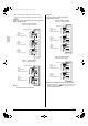
3P130767-1_En.fm Page 5 Wednesday, December 17, 2003 7:39 PM • Each time you press the operation selection button, the operation mode display will change as shown in the figure below. Example 1: In case of the remote controller “BRC1C61” and as equivalent. Display changes as below.
3P130767-1_En.fm Page 6 Wednesday, December 17, 2003 7:39 PM 3. ! EXPLANATION OF OPERATION MODE OPERATION PROCEDURE 3-1 COOLING, HEATING, AND FAN ONLY OPERATION (Refer to figure 5) Cooling mode Heating mode [PREPARATIONS] • To protect the unit, turn on the main power switch 6 hours before operation. Do not turn off the power during the heating or cooling season. This is to ensure smooth start-up.
3P130767-1_En.fm Page 7 Wednesday, December 17, 2003 7:39 PM 3-2 SETTING THE MASTER REMOTE CONTROLLER (Refer to Fig. 6) • When the system is installed as shown bellow it is necessary to designate one of the remote controllers as the master remote controller. • Only the master remote controller can select cooling, heating, or automatic operation (the last only on simultaneous cooling/heating systems).
3P130767-1_En.fm Page 8 Wednesday, December 17, 2003 7:39 PM Press the programming time button and set the time for stopping or starting the system. 2 Each time this button is pressed, the time advances or goes backward by 1 hour. • The timer can be programmed for a maximum of 72 hours. • Each time when “ ” is pushed, the time advances one hour. Each time when “ ” is pushed, the time goes back one hour. Press the timer on/off button. 3 The timer setting procedure ends.
3P130767-1_En.fm Page 9 Wednesday, December 17, 2003 7:39 PM NOTE • Be sure to install the air filter after servicing. (Missing air filter causes clogged heat exchange element.) The air filter is an optional item and the replacement is available. 5. Install the maintenance cover. Refer to page 8 (4-1, 1). For remote controllers which display the filter sign, turn on the power after maintenance, and press the filter sign reset button.
3P130767-1_En.fm Page 10 Wednesday, December 17, 2003 7:39 PM • If the display “ ” (INSPECTION), ”UNIT No.” and the OPERATION lamp flash and the “MALFUNCTION CODE” appears. OPERATION lamp UNIT No. In case of the malfunction with the code in white letters on the black background in the unit still operates. However, be sure to have it inspected and repaired and as soon as possible.
3P130767-1_Cover.