INSTALLATION MANUAL System air conditioner English Français Español REYQ72PAYD REYQ96PAYD REYQ120PAYD REYQ72PATJ REYQ96PATJ REYQ120PATJ
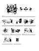
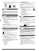
≥3/8 3 1 ≥3-7/8 (Pattern 2) ≥2 ≥2 ≥2 ≥19-5/8 3 2 1 ≥3/4 ≥3/8 ≥11-3/4 ≥7-7/8 figure 1 2 2 ≥3-7/8 4 ≥3-7/8 1 ≥3-7/8 ≥2 (Pattern 3) ≥11-3/4 ≥7-7/8 ≥15-3/4 1 ≥15-3/4 1 2 3 2 (Pattern 3) 1 ≥19-5/8 (Pattern 2) 4 1 ≥3/4 3 ≥40 ≥19-5/8 ≥40 1 ≥3/8 ≥3/8 < When installed in serial > (Pattern 1) ≥11-3/4 4 ≥60 < If installed as a single unit > (Pattern 1) ≥11-3/4 4 ≥19-5/8 3 5 4 0 ≥4 ≥60 ≥60 ≥60 (in.
1 4 3 A 1 4 1 5 3 figure 13 figure 14 1 6 2 B 2 5 2 figure 15 5 1 2 2 1 4 2 9 1 3 3 6 2 3 4 8 3 4 7 figure 16 figure 17-1 figure 17-2 3 6 2 1 1 A1P 2 9 TO IN/D UNIT TO OUT/D UNIT F1 F2 F1 F2 F1 F2 F1 F2 TO OUT/D UNIT TO IN/D UNIT F1 F2 F1 F2 TO OUT/D UNIT TO IN/D UNIT 7 7 F1 F2 F1 F2 F1 F2 8 4 F1 F2 F1 F2 F1 F2 F1 F2 F1 F2 F1 F2 F1 F2 F1 F2 8 5 figure 18 figure 19 7 1 8 L1 L2 L3 1 (A1P) 9 4 6 3 5 2 1 4 3 2 5 4 2 10 3 4 6 12 4
11 1 12 3 9 10 A 8 14 13 B 14 2 2 C Part A 4 5 Part B Part C 7 6 figure 23 7 8 9 10 1 2 1 14 3 6 2 12 3 13 4 5 : 18 : 19 15 11 2 : 16 ( : 17 ) 1 figure 24 figure 25 figure 26 1 3 4 2 1 3 2 4 5 6 7 8 5 9 1 6 2 2 5 3 7 : 13 : 14 4 figure 27 figure 28 figure 29 3 4 5 6 7 2 9 1 1 3 10 2 4 : 13 : 14 figure 30 11 : 15 ( : 16 ) 8 12 figure 31 11 10 8 12 : 15 ( : 16 )
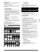
REYQ72PAYD REYQ96PAYD REYQ120PAYD REYQ72PATJ REYQ96PATJ REYQ120PATJ CONTENTS 1. FIRST OF ALL..........................................................................1 1-1. Safety considerations ........................................................1 1-2. Special notice of product ...................................................2 1-3. Disposal requirements.......................................................3 2. INTRODUCTION......................................................................
• Make sure that all wiring is secured, that specified wires are used, and that no external forces act on the terminal connections or wires. Improper connections or installation may result in fire. • Remote controller (wireless kit) transmitting distance can be shorter than expected in rooms with electronic fluorescent lamps (inverter or rapid start types). Install the indoor unit far away from fluorescent lamps as much as possible.
[DESIGN PRESSURE] Since design pressure is 478 psi, the wall thickness of pipes should be more carefully selected in accordance with the relevant local and national regulations. 1-3 Disposal requirements Dismantling of the unit, treatment of the refrigerant, oil and eventual other parts, should be done in accordance with the relevant local and national regulations. 2. INTRODUCTION 2-1 Combination • The indoor units can be installed in the following range.
Service h1 + space 2 or more h1 h2 2 or more 19 - 5/8 + 19-5/8 59 5. DANGER (Refer to figure 6) 1. Independent base (four corner type) 2. Independent base (with center support type) 3. Beam base (Horizontal) 4. Beam base (Vertical) 5. Center of the product • Do not install unit in an area where flammable materials are present due to risk of explosion resulting in serious injury or death. • Refrigerant gas in heavier air and replaces oxygen.
• Outside unit multi connection piping kit and refrigerant branching kit (sold separately) are needed for connection of piping between outside units (in case of multi system) and piping branches. Use only separately sold items selected specifically according to the outside unit multi connection piping kit, the refrigerant branching kit selection in the “6-5 Example of connection”. 6-2 Protection against contamination when installing pipes Protect the piping to prevent moisture, dirt, dust, etc.
BS Unit Liquid pipe Gas pipe Allowable length after the branch Allowable Between outside and indoor units height Between indoor and indoor units difference Between outside and outside units Between outside unit (*2) Maximum and indoor unit allowable length Between first outside unit multi connection piping kit and outside unit (in case of multi system) Multi outside system REYQ 144~192 PAYD REYQ 144~192 PATJ Single outside system REYQ 72~120 PAYD REYQ 72~120 PATJ Difference in height Difference in h
English 7 Piping between outside unit multi connection piping kits Piping between outside unit and refrigerant branch kit (part A) Piping between outside unit multi connection piping kit and outside unit (part B) Equalizer pipe (part C) For an outside unit installation, make the settings in accordance with the following figure. Outside unit The thickness and material shall be selected in accordance with local code.
8 English 0.121 0.040 (Total length (ft) of liquid piping size at φ3/8) 0.249 (Total length (ft) of liquid piping size at φ5/8) (Total length (ft) of liquid piping size at φ7/8) 0.015 (Total length (ft) of liquid piping size at φ1/4) 1.02 HEAT RECOVER SYSTEM THE AMOUNT OF REFRIGERANT REYQ72 ~ 120PAYD 7.9 lb REYQ72 ~ 120PATJ REYQ144 ~ 192PAYD 2.2 lb REYQ144 ~ 192PATJ a : φ3/4 × 15ft. b : φ3/4 × 10ft. c : φ3/8 × 5ft. d : φ3/8 × 5ft. e : φ3/8 × 5ft. f : φ3/8 × 5ft. g : φ3/8 × 5ft. h : φ3/8 × 5ft.
7. FIELD WIRING NOTE • All field wiring and components must be installed by a licensed electrician and must comply with relevant local and national regulations. • Be sure to use a dedicated power circuit. Never use a power supply shared by another appliance. • Never install a phase advancing capacitor.
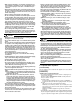
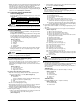
NOTE • Open the knock holes with a hammer or the like. • After knocking out the holes, we recommend you remove any burrs and paint them using the repair paint to prevent rusting. (Refer to figure 17-1, 2) • When passing wiring through the knock holes, remove burrs around the knock holes and protect the wiring with protective tape. (Refer to figure 17-1, 2) • If small animals might enter the unit, block off any gaps (hatching parts in figure 17-1, 2) with material (field supply).
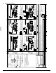
• When two wires are connected to a single terminal, connect them so that the rear sides of the crimp contacts face each other. Also, make sure the thinner wire is on top, securing the two wires simultaneously to the resin hook using the included clamp (1). Terminal Crip style terminal block Wire : narrow Wire : thick Resin hook 7-6 Procedure for Wiring Inside Units • Referring to figure 23, secure and wire the power and transmission wiring using the included clamp (1), (2), and (3).
Evacuate the system from the liquid pipe, suction gas pipe, HP/LP gas pipe and equalizer pipe shutoff valve service ports by using a vacuum pump for more than 2 hours and bring the system to –14.6 psi or less. After keeping the system under that condition for more than 1 hour, check if the vacuum gauge rises or not. If it rises, the system may either contain moisture inside or have leaks. NOTE If moisture might enter the piping, follow belows. (I.e.
To open Tightening torque The sizes of the shutoff valves on each model and the tightening torque for each size are listed in the table below. 1. Remove the cap and turn the shaft counterclockwise with the hexa- 72PA type 2. Turn it until the shaft stops. 3. Make sure to tighten the cap securely. 96PA type 120PA type φ3/8 The 120PA type corresponds to the φ1/2 - diameter onsite piping using the accessory pipe.
4. 5. 6. 7. 8. 9. 10. 11. 12. 13. 14. 15. 16. CAUTION • Make sure to use the protect tool (protective groves and goggles) when charging the refrigerant. • Due to a danger of liquid hammer, the refrigerant must not be charged over the allowable maximum amount when charging the refrigerant. • Do not perform the refrigerant charging operation under working for the BS and indoor unit. • When opening the front panel, make sure to take caution to the fan rotation during the working.
• After H2P stop blinking (about 12 minutes after turning on the power), check H2P is OFF. If H2P is ON, check the malfunction code in the remote controller of indoor unit and correct the malfunction in accordance with [Remote controller display malfunction code] in chapter 11-2-2. (3) Check the LED. And push the MODE button (BS1) once if the LED displays is not as below. H1P H2P H3P H4P H5P H6P H7P h h i h h h h (4) Push the TEST button (BS4) once. (The LED displays will change as below.
6. After completing the additional refrigerant charging, record the charging amount on the accessory “REQUEST FOR THE INDICATON” label (Installation records) and adhere it to the back side of the front panel. 11-2-2 Procedure of check operation • Check operation perform the following work. Do the check operation following below. Otherwise, malfunction code “U3” will be displayed in the remote controller and nomal operation can not be carried out.
• If the check operation was not performed at first istallation, the malfunction code “U3” will be displayed in the remote controller. Perform the check operation following “11-2-2 Procedure of Check Operation. 13-3 Checks After Test Run Perform the following checks after the test run is complete. • Record the contents of field setting. → Record them on the accessory “REQUEST FOR THE INDICATION” label. And attach the label on the back side of the front panel. • Record the installation date.
1645 Wallace Drive, Suite 110 Carrollton, TX 75006 info@daikinac.com www.daikinac.