INSTALLATION MANUAL System air conditioner REMQ8P9Y1B REMQ10P8Y1B REM(H)Q12P8Y1B REMQ14P8Y1B REMQ16P8Y1B
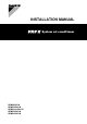
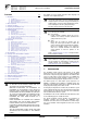
1 2 3 2 6 b c a e 4 f d 00 ≥15 00 ≥15 ≥1500 d 1 a ≥10 mm b ≥300 mm c ≥10 mm d ≥500 mm a ≥50 mm b ≥100 mm c ≥50 mm d ≥500 mm a ≥200 mm b ≥300 mm a ≥10 mm b ≥300 mm c ≥10 mm d ≥500 mm e ≥20 mm a ≥50 mm b ≥100 mm c ≥50 mm d ≥500 mm e ≥100 mm a ≥200 mm b ≥300 mm a ≥10 mm b ≥300 mm c ≥10 mm d ≥500 mm e ≥20 mm f ≥600 mm a ≥50 mm b ≥100 mm c ≥50 mm d ≥500 mm e ≥100 mm f ≥500 mm a ≥10 mm b ≥300 mm c ≥10 mm d ≥300 mm e ≥20 mm f ≥500 mm a ≥50 mm b ≥100 mm c ≥50 mm d ≥100 mm e ≥100 mm f ≥500 mm 5
12 16 max 15° A 13 ±30° A 1 1 2 1 B 1 B 1 5 12 4 3 13 15 14 1 4 1 1 B 8 2 B A 7 1 9 10 9 10 3 5 2 5 6 3 >12 0 >50 mm 0m m 4 2 6 3 2 14 16 15 18 17 1 1 TO IN/D UNIT TO OUT/D UNIT TO MULTI UNIT 8 6 F1 F2 F1 F2 Q1Q2 7 8 1 3 2 4 A1P F1 F2 F1 F2 Q1 Q2 A1P Q1 Q2 2 5 F1 F2 F1 F2 F1 F2 F1 F2 TO IN/D TO OUT/D UNIT UNIT TO IN/D TO OUT/D UNIT UNIT 9 9 A1P Q1 Q2 F1 F2 F1 F2 F1 F2 10 11 2 3 4 6 5 F1 F2 10 7 17 F1 F2 F1 F2 18 19 1 L1 L2 L3 N
CE - DECLARACION-DE-CONFORMIDAD CE - DICHIARAZIONE-DI-CONFORMITA CE - ¢H§ø™H ™YMMOPºø™H™ 06 * delineato nel e giudicato positivamente da secondo il Certificato . ** delineato nel File Tecnico di Costruzione e giudicato positivamente da (Modulo applicato). . Categoria di rischio . Fare riferimento anche alla pagina successiva. 07 * fiˆ˜ ηıÔÚ›˙ÂÙ·È ÛÙÔ Î·È ÎÚ›ÓÂÙ·È ıÂÙÈο ·fi ÙÔ Û‡Ìʈӷ Ì ÙÔ ¶ÈÛÙÔÔÈËÙÈÎfi .
настоящее заявление: 14 Název a adresa informovaného orgánu, který vydal pozitivní posouzení shody se směrnicí o tlakových zařízeních: 15 Naziv i adresa prijavljenog tijela koje je donijelo pozitivnu prosudbu o usklađenosti sa Smjernicom za tlačnu opremu: 16 A nyomástartó berendezésekre vonatkozó irányelvnek való megfelelŒséget igazoló bejelentett szervezet neve és címe: 17 Nazwa i adres Jednostki notyfikowanej, która wydała pozytywną opinię dotyczącą spełnienia wymogów Dyrektywy dot.
REMQ8P9Y1B REMQ10P8Y1B REMQ12P8Y1B CONTENTS REMHQ12P8Y1B REMQ14P8Y1B REMQ16P8Y1B Installation manual VRVIII System air conditioner Page The English text is the original instruction. Other languages are translations of the original instructions. 1. Introduction................................................................................ 1 1.1. 1.2. 1.3. 1.4. 2. 3. 4. 5. 6. The refrigerant charge of the system must be less than 100 kg.
1.1. Combination 1.2. The indoor units can be installed in the following range. ■ ■ Always use appropriate indoor units compatible with R410A. To learn which models of indoor units are compatible with R410A, refer to the product catalogs.
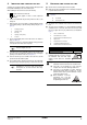
3. SELECTION OF LOCATION 11 To prevent dripping water to form a puddle underneath the unit, install a drain pan (available as option kit). This unit, both indoor and outdoor, is suitable for installation in a commercial and light industrial environment. If installed as a house-hold appliance it could cause electromagnetic interference, in which case the user may be required to take adequate measures. 12 The equipment is not intended for use in a potentially explosive atmosphere.
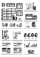
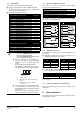
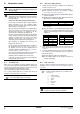
INSPECTING AND HANDLING THE UNIT At delivery, the packing should be checked and any damage should be reported immediately to the carrier claims agent. 5. Remove the four screws fixing the unit to the pallet. ■ Make sure the unit is installed level on a sufficiently strong base to prevent vibration and noise. Fragile, handle the unit with care. Do not use stands to only support the corners. (See figure 8) Keep the unit upright in order to avoid compressor damage.
6. REFRIGERANT PIPING Do not insert fingers, rods or other objects into the air inlet or outlet. When the fan is rotating at high speed, it will cause injury. 6.2. Selection of piping material 1. Foreign materials inside pipes (including oils for fabrication) must be 30 mg/10 m or less. 2. Use the following material specification for refrigerant piping: ■ Size: determine the proper size referring to chapter "6.6. Example of connection" on page 9.
6.4. 1 Connecting the refrigerant piping 2 Removing the pinched piping (See figure 6) Front connection or side connection Installation of refrigerant piping is possible as front connection or side connection (when taken out from the bottom) as shown in the figure. 1 Left-side connection 2 Front connection 3 Right-side connection Any gas or oil remaining inside the stop valve may blow off the pinched piping.
3 Connecting refrigerant piping to outdoor units All local interunit piping are field supplied except the accessory pipes. NOTE ■ Front connection: Remove the stop valve cover to connect. (See figure 9) (A) ■ Bottom connection: Remove the knockout holes on the bottom frame and route the piping under the bottom frame.
Prohibited patterns: change to pattern 1 or 2. 2 1 2 2 1 2 4 2 Branching the refrigerant piping ■ For installation of the refrigerant branching kit, refer to the installation manual delivered with the kit. (See figure 12) 2 1 1 2 To indoor unit Oil remains in piping Follow the conditions listed below: - Mount the refnet joint so that it branches either horizontally or vertically. - Mount the refnet header so that it branches horizontally.
9 Installation manual BS unit Liquid pipe Indoor unit side (2 pipes) Gas pipe A B1 g f F h 1 i y G c C d o 5 n B3 D e q 6 p B4 E r 7 H2 8 s H1 H1 2 f d 1 e B2 c B1 a h 3 g B3 A b z j i 4 B4 H3 m k 5 B5 l 6 n B outdoor multi connection piping kit 4 B2 m l y refnet header 3 B x refnet joint 2 k H3 [Example] unit 6: a+b+l≤165 m, unit 8: a+m+n+p≤165 m 7 8 H2 e 2 d B2 f 3 B3 g 4 5 B2 k j 6 l B3 m n 7 H2 o 8 KHRQ23M29T KHRQ23M64T KHRQ23M75T
F A B C D C D The refrigerant charge of the system must be less than 100 kg. This means that in case the calculated refrigerant charge is equal to or more than 95 kg you must divide your multiple outdoor system into smaller independent systems, each containing less than 95 kg refrigerant charge. For factory charge, refer to the unit name plate. How to calculate the additional refrigerant to be charged Additional refrigerant to be charged R (kg) R should be rounded off in units of 0.
11 REY(H)Q Ø 1 2 Installation manual The difference between the distance of the outdoor unit to the farthest indoor unit and the distance of the outdoor unit to the nearest indoor unit ≤40 m Indoor unit to the nearest branch kit ≤40 m For calculation of total extension length, the actual length of above pipes must be doubled (except length of main pipes and of pipes which do not have an increased pipe size).
■ Vacuum drying: Use a vacuum pump which can evacuate to –100.7 kPa (5 Torr, –755 mm Hg) 1. Evacuate the system from the liquid pipe, the suction gas pipe, the high pressure/low pressure gas pipe and the equalizer pipe stop valve service ports by using a vacuum pump for more than 2 hours and bring the system to –100.7 kPa. After keeping the system under that condition for more than 1 hour, check if the vacuum gauge rises or not. If it rises, the system may either contain moisture inside or have leaks.
Y1S~Y7S............. Solenoid valve (RMTG, 4 way valve–PPE, 4 way valve–H/E gas, RMTL, hot gas, EV bypass, RMTO) Z1C~Z10C........... Noise filter (ferrite core) Z1F...................... Noise filter (with surge absorber) 8.3. Power circuit and cable requirements A power circuit (see table below) must be provided for connection of the unit. This circuit must be protected with the required safety devices, i.e. a main switch, a slow blow fuse on each phase and an earth leakage breaker. L1,L2,L3 ..........
Minimum Zmax (Ω) Ssc value REYQ18 = REMQ8+REMQ10 0.27 1748 kVA REYQ20 = REMQ8+REMQ12 0.27 1759 kVA REYQ22 = REMQ10+REMQ12 0.25 1687 kVA REYQ24 = REMQ12+REMQ12 0.25 1698 kVA REYQ26 = REMQ10+REMQ16 0.23 1711 kVA REYQ28 = REMQ12+REMQ16 0.23 1722 kVA REYQ30 = REMQ14+REMQ16 0.22 1746 kVA REYQ32 = REMQ16+REMQ16 0.22 1746 kVA REYQ34 = REMQ8+REMQ10+REMQ16 0.23 2621 kVA REYQ36 = REMQ8+REMQ12+REMQ16 0.23 2632 kVA REYQ38 = REMQ10+REMQ12+REMQ16 0.
8.6. ■ Leading power line and transmission line Be sure to let the power line and the transmission line pass through a conduit hole. Lead the power line from the upper hole on the left side plate, from the front position of the main unit (through the conduit hole of the wiring mounting plate) or from a knock out hole to be made in the unit's bottom plate. (See figure 17) ■ 1 2 (See figure 18) Master unit(a) 2 Slave unit(a) 3 Outdoor unit A 4 Outdoor unit B Electric wiring diagram.
8.8. Outside unit ■ Be sure to follow the limits below. If the unit-to-unit cables are beyond these limits, it may result in malfunction of transmission. - Maximum wiring length: 1000 m - Total wiring length: 2000 m - Maximum interunit wiring length 30 m between outdoor units in the same system: - Maximum number of branches: 16 Field line connection: power wiring The power cord must be clamped to the plastic bracket using field supplied clamp material.
8.9. 10. CHECKING Wiring example for wiring inside unit OF UNIT AND INSTALLATION CONDITIONS See figure 22. 1 Power wiring 2 Wiring between units 3 Clamp to the electric box with field supplied clamps. 4 When routing out the power/ground wires from the right side: 5 Be sure to check the following: The piping work 1 When routing the remote control cord and inter-unit wiring, secure clearance of 50 mm or more from the power wiring.
The filled out label must be adhered on the inside of the product and in the proximity of the product charging port (e.g. on the inside of the service cover).
Example: in the following procedure there are 22 units active: Electric shock warning NOTE Wherever during this procedure, press the BS1 MODE button if something becomes unclear. ■ Close the electric box lid before turning on the main power. x "OFF"). ■ Perform the settings on the circuit board (A1P) of the outdoor unit and check the LED display after the power is on via the service lid which is in the lid of the electric box.
4 1 Measuring instrument 2 Refrigerant tank (R410A, siphon system) 3 Charge hose 4 Equalizer pipe stop valve 5 High pressure/low pressure gas pipe stop valve 6 Suction gas pipe stop valve 7 Liquid pipe stop valve 8 Refrigerant charge port 9 Valve A 10 Valve B 11 Valve C 12 To BS unit, indoor unit 13 Stop valve 14 Service port 15 Field piping 16 Refrigerant flow when pre-charging through the liquid stop valve service port (refer to step 3 on page 19) 17 Refrigerant flow when
8. When the refrigerant tank is not connected or is left with the valve closed for 30 minutes or more, the outdoor unit will stop operation and the P2 code will be displayed on the remote controller of the indoor unit. Follow the procedure as described in "3 Remote controller malfunction code display" on page 22. Operation When the following LED display is shown, open valve A and close the front panel. If the front panel is left open, the system can not operate properly during the refrigerant charging.
2 11.6.
Possible LED combinations in function of weight of additional refrigerant charge (= x) to input; kg 0 5 x=0 1 0
12.2. Checks before initial start-up Location of the dip switches, LEDs and buttons Remark that during the first running period of the unit, required power input may be higher than stated on the nameplate of the unit. This phenomenon originates from the compressor that needs elapse of a 50 hours run in period before reaching smooth operation and stable power consumption. NOTE ■ Make sure that the circuit breaker on the power supply panel of the installation is switched off.
3.2 Possible settings for function C The noise of level 3 < level 2 < level 1 ( Setting the mode The set mode can be changed with the BS1 MODE button according to the following procedure: ■ ■ H1P H2P H3P H4P H5P H6P H7P OFF For setting mode 1: Press the BS1 MODE button once, the H1P LED is off x. This mode is not available for heat recovery units. 1 For setting mode 2: Press the BS1 MODE 5 seconds, the H1P LED is on w.
12.4. Test operation 2. Press the BS3 RETURN button once to confirm. H1P H2P H3P H4P H5P H6P H7P w x Do not insert fingers, rods or other objects into the air inlet or outlet. When the fan is rotating at high speed, it will cause injury. 3. w x 4. 5. ■ the outdoor temperature must be 0°C DB~43°C DB ■ Check for wrong wiring ■ In case of a multi system, check the settings and results on the master unit. ■ Abnormalities on indoor units can not be checked for each unit individual.
Installation error Error code The refrigerant was not charged using the automatic charging function. P7 The added amount of refrigerant was not inputted after automatic charging. PF In case the test operation was interrupted or the unit was operating out of the instructed temperature range, the initial refrigerant detection has failed. U3 Remedial action Availability of the leak detection function requires the refrigerant to be charged using the automatic charging function.
6 After charging the specified quantity of refrigerant, press the BS3 RETURN button to stop the operation. Procedure for checking maximum concentration The operation will stop within 30 minutes. Check the maximum concentration level in accordance with steps 1 to 4 below and take whatever action is necessary to comply. ■ If charging is not completed after 30 minutes, set and perform the additional refrigerant charging operation again.
16. DISPOSAL REQUIREMENTS NOTES Dismantling of the unit, treatment of the refrigerant, of oil and of other parts must be done in accordance with relevant local and national legislation.
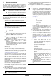
22 1 10 2 3 5 1 10 2 3 6 6 6 6 6 6 6 6 6 6 6 6 9 6 6 6 6 6 6 6 4 9 4 6 11 11 6 6 6 6 6 6 7 8 7 7 7 8 12 14 13 15 22 23 6 12 13 8 7 9 10 11 14 1 4 3 2 5 16 15 17 18 19 23 24 3 9 10 5 4 6 7 8 11 2 2 1 1 9 2 18 1 12 24 NOTES 13 14 15 16 17
4PW48463-1A Copyright © Daikin