00_CV_3PN09042-1A.fm Page 1 Thursday, March 6, 2008 7:22 PM INSTALLATION MANUAL English SYSTEM Inverter Air Conditioners Deutsch MODELS Ceiling-mounted duct type low static pressure unit FXDQ20PBVE FXDQ25PBVE FXDQ32PBVE FXDQ40NBVE FXDQ50NBVE FXDQ63NBVE FXDQ20PBVET FXDQ25PBVET FXDQ32PBVET FXDQ40NBVET FXDQ50NBVET FXDQ63NBVET Français Español Italiano ÅëëçíéêÜ READ THESE INSTRUCTIONS CAREFULLY BEFORE INSTALLATION. KEEP THIS MANUAL IN A HANDY PLACE FOR FUTURE REFERENCE.
EN60335-2-40, FXDQ20NVE, FXDQ25NVE, FXDQ32NVE, FXDQ40NVE, FXDQ50NVE, FXDQ63NVE FXDQ20NAVE, FXDQ25NAVE, FXDQ32NAVE, FXDQ40NAVE, FXDQ50NAVE, FXDQ63NAVE FXDQ20NVET, FXDQ25NVET, FXDQ32NVET, FXDQ40NVET, FXDQ50NVET, FXDQ63NVET FXD20MVE, FXD25MVE, FXD32MVE, FXD40MVE, FXD50MVE, FXD63MVE FXD20MVET, FXD25MVET, FXD32MVET, FXD40MVET, FXD50MVET, FXD63MVET FXF25LVE, FXF32LVE, FXF40LVE, FXF50LVE, FXF63LVE, FXF80LVE, FXF100LVE, FXF125LVE FXFQ25MVE, FXFQ32MVE, FXFQ40MVE, FXFQ50MVE, FXFQ63MVE, FXFQ80MVE, FXFQ100MVE, FXFQ125
01_EN_3PN09042-1A.fm Page 1 Friday, March 21, 2008 7:21 PM VRV SYSTEM Inverter Air Conditioners CONTENTS 1. 2. 3. 4. 5. 6. 7. 8. 9. 10. 11. 1. SAFETY PRECAUTIONS................................................ 1 BEFORE INSTALLATION ................................................ 2 SELECTING INSTALLATION SITE ................................. 3 PREPARATIONS BEFORE INSTALLATION.................... 4 INDOOR UNIT INSTALLATION ....................................... 5 REFRIGERANT PIPING WORK ...............
01_EN_3PN09042-1A.fm Page 2 Friday, March 21, 2008 7:21 PM 2. • • • • • Where corrosive gas, such as sulphurous acid gas, is produced. Corroding of copper pipes or soldered parts may result in refrigerant leakage. 3. Near machinery emitting electromagnetic radiation. Electromagnetic radiation may disturb the operation of the control system and result in a malfunction of the unit. 4.
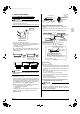
01_EN_3PN09042-1A.fm Page 3 Friday, March 21, 2008 7:21 PM Is something blocking the air outlet or inlet of either the indoor or outdoor units? It may result in insufficient cooling. Are refrigerant piping length and additional refrigerant charge noted down? The refrigerant charge in the system is not clear. *300 or more Control box Maintenance space Also review the “SAFETY PRECAUTIONS”.
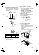
01_EN_3PN09042-1A.fm Page 4 Friday, March 21, 2008 7:21 PM 4. PREPARATIONS BEFORE INSTALLATION (1) Confirm the positional relationship between the unit and suspension bolts. (Refer to Fig. 2) • Install the inspection opening on the control box side where maintenance and inspection of the control box and drain pump are easy. Install the inspection opening also in the lower part of the unit.
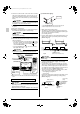
01_EN_3PN09042-1A.fm Page 5 Friday, March 21, 2008 7:21 PM (3) Main unit Force Attach the filter to the main unit while pushing down on the bends. Filter Level Force Vinyl tube (4) Tighten the upper nut. 6. In case of bottom side 5. In case of back side INDOOR UNIT INSTALLATION 〈〈As for the parts to be used for installation work, be sure to use the provided accessories and specified parts designated by our company.〉〉 (1) Install the indoor unit temporarily.
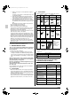
01_EN_3PN09042-1A.fm Page 6 Friday, March 21, 2008 7:21 PM • Refer to Table 1 for tightening torque. Table 1 Tightening torque Flare dimension A (mm) φ 6.4 (1/4”) 14.2 – 17.2 N·m (144 – 176 kgf·cm) 8.7 – 9.1 φ 9.5 (3/8”) 32.7 – 39.9 N·m (333 – 407 kgf·cm) 12.8 – 13.2 φ 12.7 (1/2”) 49.5 – 60.3 N·m (504 – 616 kgf·cm) 16.2 – 16.6 φ 15.9 (5/8”) 61.8 – 75.4 N·m (630 – 770 kgf·cm) 19.3 – 19.7 Flare shape 45 Ⳳ2 0 R0.4-0.
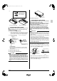
01_EN_3PN09042-1A.fm Page 7 Friday, March 21, 2008 7:21 PM 7. DRAIN PIPING WORK Large sealing pad (5) (accessory) Metal clamp (1) (accessory) Metal clamp (1) In case of PBVE, NBVE type (with drain pump) CAUTION • The connection opening on the drain piping may vary depending on the model, so check the model name and use the right method for that model. • Make sure all water is out before making the duct connection. (1) Install the drain piping.
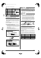
01_EN_3PN09042-1A.fm Page 8 Friday, March 21, 2008 7:21 PM 1. Remove the control box lid. Connect the remote controller and power supply (single-phase, 50 Hz 220-240 V or single-phase, 60Hz 220V) respectively to the terminal block and securely connect the earth also (as shown in the figure below). (1) Install the drain piping. Drain socket CAUTION Securely clamp the cables with the clamps (9)(10) offered as accessories as shown in Fig. 17 so that tension will not be applied on the cable connection areas.
01_EN_3PN09042-1A.fm Page 9 Friday, March 21, 2008 7:21 PM 〈 PRECAUTIONS 〉 Drain piping connections • Do not connect the drain piping directly to sewage pipes that smell of ammonia. The ammonia in the sewage might enter the indoor unit through the drain piping and corrode the heat exchanger. • Do not twist or bend the drain hose (2), so that excessive force is not applied to it. (This type of treatment may cause leaking.
01_EN_3PN09042-1A.fm Page 10 Friday, March 21, 2008 7:21 PM NOTES 1. Shows only in case of protected pipes. Use H07RN-F in case of no protection. 2. Insulated thickness : 1mm or more. 3. If the wiring is in a place where people it can be easily touched by people, install an earth leakage breaker to prevent electric shock. 4. When using an earth leakage breaker, make sure to select one useful also to protection against overcurrent and shortcircuit.
01_EN_3PN09042-1A.fm Page 11 Friday, March 21, 2008 7:21 PM [ PRECAUTIONS ] • Refer to the “REMOTE CONTROLLER INSTALLATION MANUAL” on how to install and lay the wiring for the remote controller. • See also the “Wiring Diagram plate” attached to the control box lid when laying electrical wiring. • Connect the remote controller and transmission wiring their respective terminal blocks.
01_EN_3PN09042-1A.fm Page 12 Friday, March 21, 2008 7:21 PM No. 2 system For group control or use with 2 remote controllers • When using 2 remote controllers, one must be set to “MAIN” and the other to “SUB”. Power supply single phase 50Hz 220-240V or single phase 60Hz 220V Outdoor unit MAIN/SUB CHANGEOVER Note) There is not need to set the indoor unit address when using group control. (It is automatically set when the power is turned on.
01_EN_3PN09042-1A.fm Page 13 Friday, March 21, 2008 7:21 PM [ PRECAUTIONS ] • Crossover wiring is needed when using group control and 2 remote controllers at the same time. • Connect the indoor unit at the end of the crossover wire (P1, P2) to remote controller 2 (SUB). Indoor unit 1 Indoor unit 2 Max. No. of indoor units 11-1 SETTING THE STATIC PRESSURE SELECTION • Select the SECOND CODE NO. for the resistance of the connected duct. (The SECOND CODE NO. is set to “01” when shipped.
01_EN_3PN09042-1A.fm Page 14 Friday, March 21, 2008 7:21 PM 11-4 SETTINGS FOR SEPARATELY SOLD ACCESSORIES • See the instruction manuals included with separately sold accessories for the necessary settings. 〈 When using a wireless remote controller 〉 • A wireless remote controller address needs to be set when using a wireless remote controller. See the installation manual included with the wireless remote controller for details on how to make the settings.
00_CV_3PN09042-1A.