00_CV_3P164392-2H.
Daikin.TCF.015 74736-KRQ/EMC97-4957. Daikin.TCF.015 74736-KRQ/EMC97-4957. Daikin.TCF.015 74736-KRQ/EMC97-4957. Daikin.TCF.015 74736-KRQ/EMC97-4957. Daikin.TCF.015 74736-KRQ/EMC97-4957. Daikin.TCF.015 74736-KRQ/EMC97-4957. Daikin.TCF.015 74736-KRQ/EMC97-4957. Daikin.TCF.015 74736-KRQ/EMC97-4957. Daikin.TCF.015 74736-KRQ/EMC97-4957. 74736-KRQ/EMC97-4957. Daikin.TCF.015 Daikin.TCF.015 Daikin.TCF.015 74736-KRQ/EMC97-4957. 74736-KRQ/EMC97-4957.
01_EN_3P164392-2H.fm Page 1 Friday, March 16, 2007 4:26 PM Safety Precautions • Read these Safety Precautions carefully to ensure correct installation. • This manual classifies the precautions into WARNING and CAUTION. Be sure to follow all the precautions below: they are all important for ensuring safety. WARNING...............Failure to follow any of WARNING is likely to result in such grave consequences as death or serious injury. CAUTION...............
01_EN_3P164392-2H.fm Page 2 Friday, March 16, 2007 4:26 PM Accessories Accessories supplied with the outdoor unit: (A) Installation Manual 1 (B) Drain plug (C) Reducer assy 1 1 There is on the bottom packing case. There is on the bottom packing case. (2MXS52*, 2AMX52*, 3MXS52*, 3AMX52*, 4MKS58*) (D) Screw bag (For fixing electrical wire anchor bands) (E) Refrigerant charge label 1 1 There is on the bottom packing case.
01_EN_3P164392-2H.fm Page 3 Friday, March 16, 2007 4:26 PM Indoor/Outdoor Unit Installation Drawings For installation of the indoor units, refer to the installation manual which was provided with the units. (The diagram shows a wall-mounted indoor unit.) CAUTION 1) Do not connect the embedded branch piping and the outdoor unit when only carrying out piping work without connecting the indoor unit in order to add another indoor unit later.
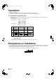
01_EN_3P164392-2H.fm Page 4 Friday, March 16, 2007 4:26 PM Installation • Install the unit horizontally. • The unit may be installed directly on a concrete verandah or a solid place if drainage is good. • If the vibration may possibly be transmitted to the building, use a vibration-proof rubber (field supply). 1. Connections (connection port) Install the indoor unit according to the table below, which shows the relationship between the class of indoor unit and the corresponding port.
01_EN_3P164392-2H.fm Page 5 Friday, March 16, 2007 4:26 PM Outdoor Unit Installation Guideline • Where a wall or other obstacle is in the path of outdoor unit’s intake or exhaust airflow, follow the installation guidelines below. • For any of the below installation patterns, the wall height on the exhaust side should be 1200mm or less.
01_EN_3P164392-2H.fm Page 6 Friday, March 16, 2007 4:26 PM Refrigerant Piping Work 1. Installing outdoor unit 1) When installing the outdoor unit, refer to “Precautions for Selecting the Location” and the “Indoor/Outdoor Unit Installation Drawings”. 2) If drain work is necessary, follow the procedures below. 2. Drain work 1) Use drain plug for drainage.
01_EN_3P164392-2H.fm Page 7 Friday, March 16, 2007 4:26 PM Refrigerant Piping Work 4. Purging air and checking gas leakage 1) When piping work is completed, it is necessary to purge the air and check for gas leakage. WARNING 1) 2) 3) 4) Do not mix any substance other than the specified refrigerant (R410A) into the refrigeration cycle. When refrigerant gas leaks occur, ventilate the room as soon and as much as possible.
01_EN_3P164392-2H.fm Page 8 Friday, March 16, 2007 4:26 PM 5. Refilling the refrigerant Check the type of refrigerant to be used on the machine nameplate. Precautions when adding R410A Fill from the liquid pipe in liquid form. It is a mixed refrigerant, so adding it in gas form may cause the refrigerant composition to change, preventing normal operation. 1) Before filling, check whether the cylinder has a siphon attached or not.
01_EN_3P164392-2H.fm Page 9 Friday, March 16, 2007 4:26 PM Refrigerant Piping Work 7. Refrigerant piping work Wall Be sure to place a cap. Cautions on pipe handling Rain If no flare cap is available, cover the flare mouth with tape to keep dirt or water out. 1) Protect the open end of the pipe against dust and moisture. 2) All pipe bends should be as gentle as possible. Use a pipe bender for bending. (Bending radius should be 30 to 40mm or larger.
01_EN_3P164392-2H.fm Page 10 Friday, March 16, 2007 4:26 PM How to Use Reducers No.1 φ15.9 → φ12.7 No.2 φ12.7 → φ9.5 Gasket (1) No.3 φ15.9 → φ12.7 No.4 φ12.7 → φ9.5 No.5 φ15.9 → φ9.5 Gasket (2) No.6 φ15.9 → φ9.5 Reduce and gasket Use the reducers supplied with the unit as described below. 1) Connecting a pipe of φ12.7 to a gas pipe connection port for φ15.9: No. 1 Be sure to attach the gasket. Inter-unit piping No. 3 Flare nut (for φ15.
01_EN_3P164392-2H.fm Page 11 Friday, March 16, 2007 4:26 PM Pump Down Operation In order to protect the environment, be sure to pump down when relocating or disposing of the unit. 1) Remove the valve lid from liquid shut-off valve and gas shutoff valve. 2) Carry out forced cooling operation. 3) After five to ten minutes, close the liquid shut-off valve with a hexagonal wrench. 4) After two to three minutes, close the gas shut-off valve and stop forced cooling operation. 1.
01_EN_3P164392-2H.fm Page 12 Friday, March 16, 2007 4:26 PM Wiring WARNING 1) Do not use tapped wires, stand wires, extensioncords, or starbust connections, as they may cause overheating, electrical shock, or fire. 2) Do not use locally purchased electrical parts inside the product. (Do not branch the power for the drain pump, etc., from the terminal block.) Doing so may cause electric shock or fire. 3) Be sure to install an earth leak detector. (One that can handle higher harmonics.
01_EN_3P164392-2H.fm Page 13 Friday, March 16, 2007 4:26 PM Priority Room Setting • To use priority room setting, initial settings must be made when the unit is installed. Explain the priority room setting, as described below, to the customer, and confirm whether or not the customer wants to use priority room setting. Setting it in the guest and living rooms is convenient. 1.
01_EN_3P164392-2H.fm Page 14 Friday, March 16, 2007 4:26 PM Night Quiet Mode Setting • If night quiet mode is to be used, initial settings must be made when the unit is installed. Explain night quiet mode, as described below, to the customer, and confirm whether or not the customer wants to use night quiet mode. Service PC-board About night quiet mode The night quiet mode function reduces operating noise of the outdoor unit at nighttime.
01_EN_3P164392-2H.fm Page 15 Friday, March 16, 2007 4:26 PM Test Run and Final Check • Before starting the test run, measure the voltage at the primary side of the safety breaker. Check that it is 220-240V. • Check that all liquid and gas shut-off valves are fully open. • Check that piping and wiring all match. The wiring error check can be conveniently used for underground wiring and other wiring that cannot be directly checked. 1.
01_EN_3P164392-2H.fm Page 16 Friday, March 16, 2007 4:26 PM 2. Test run and final check 1) To test cooling, set for the lowest temperature. To test heating, set for the highest temperature. (Depending on the room temperature, only heating or cooling (but not both) may be possible.) 2) After the unit is stopped, it will not start again (heating or cooling) for approximately 3 minutes. 3) During the test run, first check the operation of each unit individually.
00_CV_3P164392-2H.fm Page 2 Friday, March 9, 2007 11:18 AM Two-dimensional bar code is a code for manufacturing.