SiUS39 - 601 RXYQ72, 96, 144, 168, 192MTJU R-410A Heat Pump 60Hz RXYQ72MTJU RXYQ96MTJU RXYQ144MTJU RXYQ168MTJU RXYQ192MTJU
SiUS39-601 R-410A Heat Pump 60Hz 1. Introduction ................................................................................................ vi 1.1 Safety Cautions ............................................................................................vi 1.2 PREFACE .................................................................................................... x Part 1 General Information .............................................................. 1 1. Model Names of Indoor/Outdoor Units.
SiUS39-601 3.7 Pressure Equalization prior to Startup........................................................ 48 4. Protection Control .....................................................................................49 4.1 4.2 4.3 4.4 4.5 High Pressure Protection Control............................................................... 49 Low Pressure Protection Control................................................................ 50 Discharge Pipe Protection Control ..................................
SiUS39-601 2.10 “C5” Indoor Unit: Malfunction of Thermistor (R3T) for Gas Pipes.............. 132 2.11 “C9” Indoor Unit: Malfunction of Thermistor (R1T) for Suction Air............. 133 2.12 “CJ” Indoor Unit: Malfunction of Thermostat Sensor in Remote Controller ................................................................................ 134 2.13 “E1” Outdoor Unit: PC Board Defect .......................................................... 135 2.14 “E3” Outdoor Unit: Actuation of High Pressure Switch ..
SiUS39-601 2.46 “U5” Indoor Unit: Malfunction of Transmission Between Remote Controller and Indoor Unit........................................................... 180 2.47 “U7” Indoor Unit: Malfunction of Transmission Between Outdoor Units ............................................................................ 181 2.48 “U8” Indoor Unit: Malfunction of Transmission Between Main and Sub Remote Controllers .................................................................... 183 2.
SiUS39-601 2. Wiring Diagrams for Reference...............................................................223 2.1 Outdoor Unit ............................................................................................. 223 2.2 Field Wiring .............................................................................................. 224 2.3 Indoor Unit................................................................................................ 226 3. List of Electrical and Functional Parts ..........
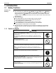
Introduction SiUS39-601 1. Introduction 1.1 Safety Cautions Cautions and Warnings Be sure to read the following safety cautions before conducting repair work. The caution items are classified into “ Warning” and “ Caution”. The “ Warning” items are especially important since they can lead to death or serious injury if they are not followed closely. The “ Caution” items can also lead to serious accidents under some conditions if they are not followed.
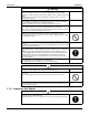
SiUS39-601 Introduction Caution Do not repair the electrical components with wet hands. Working on the equipment with wet hands can cause an electrical shock. Do not clean the air conditioner by splashing water. Washing the unit with water can cause an electrical shock. Be sure to provide the grounding when repairing the equipment in a humid or wet place, to avoid electrical shocks. Be sure to turn off the power switch and unplug the power cable when cleaning the equipment.
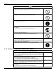
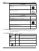
Introduction SiUS39-601 Warning Be sure to use an exclusive power circuit for the equipment, and follow the technical standards related to the electrical equipment, the internal wiring regulations and the instruction manual for installation when conducting electrical work. Insufficient power circuit capacity and improper electrical work can cause an electrical shock or fire. Be sure to use the specified cable to connect between the indoor and outdoor units.
SiUS39-601 Introduction Warning If the power cable and lead wires have scratches or deteriorated, be sure to replace them. Damaged cable and wires can cause an electrical shock, excessive heat generation or fire. Do not use a joined power cable or extension cable, or share the same power outlet with other electrical appliances, since it can cause an electrical shock, excessive heat generation or fire.
Introduction 1.2 SiUS39-601 PREFACE Thank you for your continued patronage of Daikin products. This is the new service manual for Daikin's Year 2006 VRV series Heat Pump System. Daikin offers a wide range of models to respond to building and office air conditioning needs. We are confident that customers will be able to find the models that best suit their needs. This service manual contains information regarding the servicing of VRV series Heat Pump System. Oct.
SiUS39-601 Part 1 General Information 1. Model Names of Indoor/Outdoor Units........................................................2 2. External Appearance...................................................................................3 2.1 Indoor Units .................................................................................................. 3 2.2 Outdoor Units ............................................................................................... 3 3. Model Selection.................
Model Names of Indoor/Outdoor Units SiUS39-601 1.
SiUS39-601 External Appearance 2. External Appearance 2.
Model Selection SiUS39-601 3. Model Selection VRV Heat Pump Series Connectable Indoor Units Number and Capacity 6 ton 8 ton 12 ton 14 ton 16 ton System name Ton RXYQ72M RXYQ96M RXYQ144M RXYQ168M RXYQ192M Outdoor unit 1 RXYQ72M RXYQ96M RXYQ72M RXYQ72M RXYQ96M Outdoor unit 2 — — RXYQ72M RXYQ96M RXYQ96M Total number of connectable indoor units Total Capacity Index of Indoor Units to be Connected 12 16 20 20 20 50.5~93.5 67.5~124.5 101~187 118~218 134.5~249.
SiUS39-601 Part 2 Specifications 1. Specifications ..............................................................................................6 1.1 Outdoor Units ............................................................................................... 6 1.2 Indoor Units ................................................................................................
Specifications SiUS39-601 1. Specifications 1.1 Outdoor Units Model Name ★1 Cooling Capacity ★2 Heating Capacity Casing Color Dimensions: (H×W×D) Heat Exchanger Type Piston Displacement Number of Revolutions Comp. Motor Output × Number of Units Starting Method Type Motor Output Fan Air Flow Rate Drive Liquid Pipe Connecting Gas Pipe Pipes Discharge Gas Pipe Machine Weight (Mass) ★3 Sound Level (Reference Value) Btu / h Btu / h in m3/h r.p.
SiUS39-601 Specifications Model Name ★1 Cooling Capacity ★2 Heating Capacity Casing Color Dimensions: (H×W×D) Heat Exchanger Type Piston Displacement Number of Revolutions Comp.
Specifications SiUS39-601 Model Name (Combination Unit) Model Name (Independent Unit) ★1 Cooling Capacity ★2 Heating Capacity Casing Color Dimensions: (H×W×D) Heat Exchanger Type Piston Displacement Number of Revolutions Comp. Motor Output × Number of Units Starting Method Type Motor Output Fan Air Flow Rate Drive Liquid Pipe ★3 Connecting Gas Pipe ★3 Pipes Oil Equalizing Pipe Machine Weight (Mass) Btu / h Btu / h in m3/h r.p.
SiUS39-601 Specifications Model Name (Combination Unit) Model Name (Independent Unit) ★1 Cooling Capacity ★2 Heating Capacity Casing Color Dimensions: (H×W×D) Heat Exchanger Type Piston Displacement Number of Revolutions Comp. Motor Output × Number of Units Starting Method Type Motor Output Fan Air Flow Rate Drive Liquid Pipe ★3 Connecting Gas Pipe ★3 Pipes Oil Equalizing Pipe Machine Weight (Mass) Btu / h Btu / h in m3/h r.p.
Specifications SiUS39-601 Model Name (Combination Unit) Model Name (Independent Unit) ★1 Cooling Capacity ★2 Heating Capacity Casing Color Dimensions: (H×W×D) Heat Exchanger Type Piston Displacement Number of Revolutions Comp.
SiUS39-601 1.
Specifications SiUS39-601 Ceiling Mounted Cassette Type (Multi-flow) Model FXFQ30MVJU ★1 Cooling Capacity Btu/h Btu/h ★2 Heating Capacity Casing / Color Dimensions: (H×W×D) Rows × Stages × FPI Coil (Cross Fin Coil) Face Area Model Type Motor Output Fan Air Flow Rate (H/L) Drive Temperature Control in ft² HP cfm Sound Absorbing Thermal Insulation Material Piping Connections Liquid Pipes Gas Pipes in in Drain Pipe in Machine Weight (Mass) ★4 Sound Level (H/L) Safety Devices Refrigerant Control
SiUS39-601 Specifications Slim Ceiling Mounted Duct Type Model ★1 Cooling Capacity Btu/h Btu/h ★2 Heating Capacity Casing / Color Dimensions: (H×W×D) Rows × Stages × FPI Coil (Cross Fin Coil) Face Area Model Type Motor Output Fan Air Flow Rate (H/L) External Static Pressure ★4 Drive in ft² HP cfm Pa Temperature Control Sound Absorbing Thermal Insulation Material Air Filter Liquid Pipes in Gas Pipes in Piping Connections Drain Pipe in Machine Weight (Mass) ★5 Sound Level (H/L) Lbs dBA Safety Device
Specifications SiUS39-601 Slim Ceiling Mounted Duct Type Model ★1 Cooling Capacity ★2 Heating Capacity Casing / Color Dimensions: (H×W×D) Rows × Stages × FPI Coil (Cross Fin Coil) Face Area Model Type Motor Output Fan Air Flow Rate (H/L) External Static Pressure ★4 Drive Btu/h Btu/h in ft² HP cfm Pa Temperature Control Sound Absorbing Thermal Insulation Material Air Filter Liquid Pipes in Gas Pipes in Piping Connections Drain Pipe in Machine Weight (Mass) Lbs dBA ★5 Sound Level (H/L) Safety Devices
SiUS39-601 Specifications Ceiling Mounted Built-in Type Model ★1 Cooling Capacity Btu/h Btu/h ★2 Heating Capacity Casing / Color Dimensions: (H×W×D) Rows × Stages × FPI Coil (Cross Fin Coil) Face Area Model Type Motor Output Fan Air Flow Rate (H/L) External Static Pressure ★4 Drive in ft² HP cfm in.
Specifications SiUS39-601 Ceiling Mounted Built-in Type Model ★1 Cooling Capacity Btu/h Btu/h ★2 Heating Capacity Casing / Color Dimensions: (H×W×D) Rows × Stages × FPI Coil (Cross Fin Coil) Face Area Model Type Motor Output Fan Air Flow Rate (H/L) External Static Pressure ★4 Drive in ft² HP cfm in.
SiUS39-601 Specifications Ceiling Mounted Duct Type Model ★1 Cooling Capacity Btu/h Btu/h ★2 Heating Capacity Casing / Color Dimensions: (H×W×D) Rows × Stages × FPI Coil (Cross Fin Coil) Face Area Model Type Motor Output Fan Air Flow Rate (H/L) External Static Pressure ★4 Drive in ft² HP cfm in.
Specifications SiUS39-601 Ceiling Suspended Type Model ★1 Cooling Capacity Btu/h Btu/h ★2 Heating Capacity Casing / Color Dimensions: (H×W×D) Rows × Stages × FPI Coil (Cross Fin Coil) Face Area Model Type Motor Output Fan Air Flow Rate (H/L) Drive in ft² W cfm Temperature Control Sound Absorbing Thermal Insulation Material Air Filter Liquid Pipes in Gas Pipes in Piping Connections Drain Pipes in Machine Weight (Mass) ★4 Sound Level (H/L) Safety Devices Refrigerant Control Connectable Outdoor Unit St
SiUS39-601 Specifications Wall Mounted Type Model FXAQ07MVJU FXAQ09MVJU ★1 Cooling Capacity Btu/h 7,500 9,500 12,000 ★2 Heating Capacity Btu/h 8,500 White (3.0Y8.5/0.5) 11–3/8×31–1/4×9 2×14×17 1.73 QCL9661M Cross Flow Fan 0.054 260/160 Direct Drive Microprocessor Thermostat for Cooling and Heating Foamed Polystyrene / Foamed Polyethylene Resin Net (Washable) φ1/4 (Flare Connection) φ1/2 (Flare Connection) VP13 (External Dia. 11/16 Internal Dia.
Specifications SiUS39-601 Wall Mounted Type Model ★1 Cooling Capacity Btu/h ★2 Heating Capacity Btu/h Casing Color Dimensions: (H×W×D) Rows × Stages × FPI Coil (Cross Fin Coil) Face Area Model Type Motor Output Fan Air Flow Rate (H/L) Drive Temperature Control in ft² HP cfm Sound Absorbing Thermal Insulation Material Air Filter Piping Connections Liquid Pipes Gas Pipes Drain Pipe Machine Weight (Mass) ★4 Sound Level (H) Safety Devices Refrigerant Control Connectable outdoor unit Standard Accessor
SiUS39-601 Specifications Floor Standing Type Model ★1 Cooling Capacity Btu/h Btu/h ★2 Heating Capacity Casing Color Dimensions: (H×W×D) Coil (Cross Rows × Stages × FPI Fin Coil) Face Area Model Type Motor Output Fan Air Flow Rate (H/L) Drive in ft² HP cfm Temperature Control Sound Absorbing Thermal Insulation Material Air Filter Liquid Pipes in Piping Gas Pipes in Connections Drain Pipe in Machine Weight (Mass) Lbs ★4 Sound Level (H/L) dBA Safety Devices Refrigerant Control Connectable Outdoor Unit
Specifications SiUS39-601 Concealed Floor Standing Type Model ★1 Cooling Capacity Btu/h Btu/h ★2 Heating Capacity Casing Color Dimensions: (H×W×D) Coil (Cross Rows × Stages × FPI Fin Coil) Face Area Model Type Motor Output Fan Air Flow Rate (H/L) Drive in ft² HP cfm Temperature Control Sound Absorbing Thermal Insulation Material Air Filter Liquid Pipes in Piping Gas Pipes in Connections Drain Pipe in Machine Weight (Mass) Lbs ★4 Sound Level (H/L) dBA Safety Devices Refrigerant Control Connectable Ou
SiUS39-601 Part 3 Refrigerant Circuit 1. Refrigerant Circuit .....................................................................................24 1.1 RXYQ72M, 96M ......................................................................................... 24 2. Functional Parts Layout ............................................................................26 2.1 RXYQ72M, 96M ......................................................................................... 26 3.
Refrigerant Circuit SiUS39-601 1. Refrigerant Circuit 1.1 RXYQ72M, 96M No. in refrigerant Symbol system diagram Major Function A M1C B M2C D M1F Inverter fan Since the system is of air heat exchanging type, the fan is operated at 8-step rotation speed by using the inverter. E Y1E Electronic expansion valve (Main: EV1) While in heating operation, PI control is applied to keep the outlet superheated degree of air heat exchanger constant.
SiUS39-601 Refrigerant Circuit RXYQ72M, 96M J 8 S U L D E F 6 7 I 1 2 G M K T V N Q P 4 3 B A O 9 H 4D042651A Refrigerant Circuit 25
Functional Parts Layout SiUS39-601 2. Functional Parts Layout 2.
SiUS39-601 Refrigerant Flow for Each Operation Mode 3.
Refrigerant Flow for Each Operation Mode SiUS39-601 Cooling Oil Return Indoor unit operation Fan ON " ON " Fan OFF " OFF " Fan OFF " ON " Heat exchanger Heat exchanger Heat exchanger Fan Fan Fan High temperature, high pressure gas High temperature, high pressure liquid Low temperature, low pressure EXV : Normal control Filter Filter Indoor unit EXV : 200 pls EXV : 200 pls Filter Filter Indoor unit Filter Filter Indoor unit Thermostat "ON" Thermostat "OFF" 5/16 S To other outdoor unit
SiUS39-601 Refrigerant Flow for Each Operation Mode Heating Oil Return & Defrost Indoor unit operation Fan OFF " ON " Fan OFF " OFF " Fan OFF " ON " Heat exchanger Heat exchanger Heat exchanger Fan Fan Fan High temperature, high pressure gas High temperature, high pressure liquid Low temperature, low pressure EXV : 512 pls Filter Filter Indoor unit EXV : 512 pls EXV : 512 pls Filter Filter Indoor unit Filter Filter Indoor unit Thermostat "ON" Thermostat "OFF" 5/16 S To other outdoo
Refrigerant Flow for Each Operation Mode SiUS39-601 Heating Operation Indoor unit operation Fan ON Fan LL Fan OFF Heat exchanger Heat exchanger Heat exchanger Fan Fan High temperature, high pressure gas High temperature, high pressure liquid Low temperature, low pressure Fan EXP : Normal control Filter Filter Indoor unit EXV : 200 pls EXV : 200 pls Filter Filter Indoor unit Filter Filter Indoor unit Thermostat "ON" Thermostat "OFF" 5/16 30 S To other outdoor unit oil equalizing pipe S
SiUS39-601 Part 4 Function 1. Operation Mode ........................................................................................32 2. Basic Control.............................................................................................33 2.1 2.2 2.3 2.4 Normal Operation ....................................................................................... 33 Compressor PI Control...............................................................................
Operation Mode SiUS39-601 1.
SiUS39-601 Basic Control 2. Basic Control 2.
Basic Control 2.2 SiUS39-601 Compressor PI Control Compressor PI Control Carries out the compressor capacity PI control to maintain Te at constant during cooling operation and Tc at constant during heating operation to ensure stable unit performance. [Cooling operation] Controls compressor capacity to adjust Te to achieve target value (TeS). Te setting L M (Normal) H (factory setting) 37.
SiUS39-601 Basic Control Compressor Operating Priority Each compressor operates in the following order of priority. INV: Inverter compressor STD1: Standard compressor 1 RXYQ72M RXYQ96M No. 1 No. 2 INV INV STD1 STD1 RXYQ96M RXYQ72M STEP 1 2 3 4 5 6 7 8 9 10 11 12 13 14 15 16 17 18 19 20 21 22 23 24 25 26 27 28 29 No. 1 No.
Basic Control SiUS39-601 Compressor Operating Priority Each compressor operates in the following order of priority. INV: Inverter compressor STD1: Standard compressor 1 RXYQ144M No. 1 No. 3 No. 2 No. 4 No. 1 No. 3 No. 2 No. 4 No. 2 No. 4 No. 1 No. 3 No. 2 No. 4 No. 1 No.
SiUS39-601 Basic Control Compressor Operating Priority Each compressor operates in the following order of priority. INV: Inverter compressor STD1: Standard compressor 1 RXYQ192M No. 1 No. 3 No. 2 No. 4 No. 2 No. 4 No. 1 No.
Basic Control 2.3 SiUS39-601 Electronic Expansion Valve PI Control Main Motorized Valve EV1 Control Carries out the motorized valve (Y1E) PI control to maintain the evaporator outlet superheated degree (SH) at constant during heating operation to make maximum use of the outdoor unit heat exchanger (evaporator).
SiUS39-601 2.4 Basic Control Cooling Operation Fan Control In cooling operation with low outdoor air temperature, this control is used to provide the adequate amount of circulation air with liquid pressure secured by high pressure control using outdoor unit fan.
Special Control SiUS39-601 3. Special Control 3.1 Startup Control 3.1.
SiUS39-601 3.2 Special Control Oil Return Operation 3.2.
Special Control SiUS39-601 3.2.
SiUS39-601 3.
Special Control 3.4 SiUS39-601 Pump-down Residual Operation 3.4.
SiUS39-601 3.
Special Control 3.6 SiUS39-601 Stopping Operation 3.6.
SiUS39-601 Special Control 3.6.2 Stopping Operation of Slave Units During Master Unit is in Operation with Multi-Outdoor-Unit System In cooling operation: The system operates in Mode A or Mode B listed in the table below.
Special Control 3.
SiUS39-601 Protection Control 4. Protection Control 4.1 High Pressure Protection Control This high pressure protection control is used to prevent the activation of protection devices due to abnormal increase of high pressure and to protect compressors against the transient increase of high pressure.
Protection Control 4.2 SiUS39-601 Low Pressure Protection Control This low pressure protection control is used to protect compressors against the transient decrease of low pressure. [In cooling operation] Low pressure not limited Pe: LP pressure sensor detection value for master unit Pe>58 psi Pe<50 psi Low pressure limited All STD compressors stop. Pe<36 psi Master unit:52 Hz + OFF Slave unit:Stop Pe<10 psi When occurring 3 times within 30 min., the malfunction code “ E4 ” is output.
SiUS39-601 4.3 Protection Control Discharge Pipe Protection Control This discharge pipe protection control is used to protect the compressor internal temperature against a malfunction or transient increase of discharge pipe temperature. ★ Each compressor performs the discharge pipe temperature protection control individually in the following sequence. [INV compressor] Discharge pipe temp.
Protection Control 4.4 SiUS39-601 Inverter Protection Control Inverter current protection control and inverter fin temperature control are performed to prevent tripping due to a malfunction, or transient inverter overcurrent, and fin temperature increase.
SiUS39-601 4.5 Protection Control STD Compressor Overload Protection This control is used to prevent abnormal heating due to overcurrent to the compressor resulting from failures of STD compressor such as locking. current > 30A STD compressor ON OC function →MgS off MgS Reset Demand to operate. CT detection current value>A for more than 3 sec. A 28.8A STD compressor OFF for 30 min. When occurring 3 times within 90 minutes, the malfunction code “ E6 ”is output.
Other Control SiUS39-601 5. Other Control 5.1 Outdoor Unit Rotation In the case of multi-outdoor-unit system, this outdoor unit rotation is used to prevent the compressor from burning out due to unbalanced oil level between outdoor units. [Details of outdoor unit rotation] In the case of multi-outdoor-unit system, each outdoor unit is given an operating priority for the control. Outdoor unit rotation makes it possible to change the operating priority of outdoor units.
SiUS39-601 5.2 Other Control Emergency Operation If the compressor cannot operate, this control inhibits any applicable compressor or outdoor unit from operating to perform emergency operation only with the operative compressor or outdoor unit. Caution "For making a compressor unable to operate due to malfunction, etc., be sure to conduct the work with emergency operation setting. Never execute work such as disconnection of the power cable from magnet contactor.
Other Control SiUS39-601 5.2.3 In The Case of Multi-Outdoor-Unit System (RXYQ144, 168, 192MTJU) Automatic backup operation With multi-outdoor-unit system, if a certain outdoor unit system malfunctions (i.e., the system stops and indoor unit remote controller displays the malfunction), by resetting the system with the indoor unit remote controller, the applicable outdoor unit is inhibited from operating for 8 hours, thus making it possible to perform emergency operation automatically.
SiUS39-601 5.3 Other Control Demand Operation In order to save the power consumption, the capacity of outdoor unit is saved with control forcibly by using “Demand 1 Setting” or “Demand 2 Setting”. To operate the unit with this mode, additional setting of “Continuous Demand Setting” or external input by external control adapter is required. [Demand 1 setting] Setting Demand 1 setting 1 Demand 1 setting 2 (factory setting) Demand 1 setting 3 Standard for upper limit of power consumption Approx.
Outline of Control (Indoor Unit) SiUS39-601 6. Outline of Control (Indoor Unit) 6.1 Drain Pump Control 1. The drain pump is controlled by the ON/OFF buttons (4 button (1) - (4) given in the figure below). 6.1.1 When the Float Switch is Tripped While the Cooling Thermostat is ON: ∗ 1. The objective of residual operation is to completely drain any moisture adhering to the fin of the indoor unit heat exchanger when the thermostat goes off during cooling operation. 6.1.
SiUS39-601 Outline of Control (Indoor Unit) 6.1.3 When the Float Switch is Tripped During Heating Operation: During heating operation, if the float switch is not reset even after the 5 minutes operation, 5 seconds stop, 5 minutes operation cycle ends, operation continues until the switch is reset. 6.1.
Outline of Control (Indoor Unit) 6.2 SiUS39-601 Thermostat Sensor in Remote Controller Temperature is controlled by both the thermostat sensor in remote controller and air suction thermostat in the indoor unit. (This is however limited to when the field setting for the thermostat sensor in remote controller is set to “Use.
SiUS39-601 Heating Outline of Control (Indoor Unit) When heating, the hot air rises to the top of the room, resulting in the temperature being lower near the floor where the occupants are. When controlling by body thermostat sensor only, the unit may therefore be turned off by the thermostat before the lower part of the room reaches the preset temperature.
Outline of Control (Indoor Unit) 6.3 SiUS39-601 Freeze Prevention Freeze Prevention by Off Cycle (Indoor Unit) When the temperature detected by liquid pipe temperature thermistor (R2T) of the indoor unit heat exchanger drops too low, the unit enters freeze prevention operation in accordance with the following conditions, and is also set in accordance with the conditions given below. Conditions for starting freeze prevention: Temperature is 30°F or less for total of 40 min.
SiUS39-601 Part 5 Test Operation 1. Test Operation ..........................................................................................64 1.1 Procedure and Outline ............................................................................... 64 1.2 Operation When Power is Turned On ........................................................ 67 2. Outdoor Unit PC Board Layout .................................................................68 3. Field Setting ..........................................
Test Operation SiUS39-601 1. Test Operation 1.1 Procedure and Outline Follow the following procedure to conduct the initial test operation after installation. 1.1.1 Check Work Prior to Turn Power Supply on 1.1.2 Turn Power on Turn outdoor unit power on. { Be sure to turn the power on 6 hours before starting operation to protect compressors. (to power on clankcase heater) Carry out field setting on outdoor PC board { For field settings, refer to “Field Settings” on and after P81.
SiUS39-601 Test Operation 1.1.3 Check Operation * During check operation, mount front panel to avoid the misjudging. * Check operation is mandatory for normal unit operation. (When the check operation is not executed, alarm code "U3" will be displayed.) On completion of test operation, LED on outdoor unit PC board displays the following. H3P ON: Normal completion H2P and H3P ON: Abnormal completion →Check the indoor unit remote controller for abnormal display and correct it.
Test Operation SiUS39-601 Malfunction code In case of an alarm code displayed on remote controller: Cause of trouble due to faulty installation work Closed stop valve of outdoor unit Reversed phase in power cable connection for outdoor unit Electric power for outdoor or indoor unit is not supplied.
SiUS39-601 1.2 Test Operation Operation When Power is Turned On 1.2.1 When Turning On Power First Time The unit cannot be run for up to 12 minutes to automatically set the master power and address (indoor-outdoor address, etc.). Status Outdoor unit Test lamp H2P .... Blinks Can also be set during operation described above. Indoor unit If ON button is pushed during operation described above, the “UH” malfunction indicator blinks. (Returns to normal when automatic setting is complete.) 1.2.
Outdoor Unit PC Board Layout SiUS39-601 2.
SiUS39-601 Field Setting 3. Field Setting 3.1 Field Setting from Remote Controller Individual function of indoor unit can be changed from the remote controller. At the time of installation or after service inspection / repair, make the local setting in accordance with the following description. Wrong setting may cause malfunction. (When optional accessory is mounted on the indoor unit, setting for the indoor unit may be required to change. Refer to information in the option handbook.) 3.1.
Field Setting SiUS39-601 3.1.2 Wireless Remote Controller - Indoor Unit BRC7C812 BRC4C82 BRC7E818 BRC7E83 1. When in the normal mode, push the button for 4 seconds or more, and operation then enters the “field set mode.” 2. Select the desired “mode No.” with the button. 3. Pushing the button, select the first code No. 4. Pushing the button, select the second code No. 5. Push the timer button and check the settings. 6. Push the button to return to the normal mode.
SiUS39-601 Field Setting 3.1.3 Simplified Remote Controller BRC2A71 Group No. setting by simplified remote controller. 1. Remove the cover of remote controller. 2. While in normal mode, press the [BS6] BUTTON (field set) to enter the FIELD SET MODE. 3. Select the mode No. [00] with [BS2] BUTTON (temperature setting ▲) and [BS3] BUTTON (temperature setting ▼). 4. Select the group No. with [BS9] BUTTON (set A) and [BS10] BUTTON (set B). (Group Nos. increase in the order of 1-00, 1-01......1-15, 2-00,....
Field Setting SiUS39-601 3.1.4 Setting Contents and Code No. – VRV Unit VRV Mode Setting Setting Contents Switch system No. indoor Note 2 No. unit 10(20) 0 Filter contamination heavy/ settings light (Setting for display time to clean air filter) (Sets display time to clean air filter to half when there is heavy filter contamination.) Super long life filter Long life filter Standard filter 1 2 3 12(22) 0 1 2 3 4 13(23) 5 0 1 3 4 5 15(25) 1 2 3 5 6 Note: 72 Second Code No.
SiUS39-601 Field Setting 3.1.
Field Setting SiUS39-601 External ON/OFF input This input is used for "ON / OFF operation" and "Protection device input" from the outside. The input is performed from the T1-T1 terminal of the operation terminal block (X1A) in the electric component box. F2 T1 T2 Forced stop Input A Setting Table Mode No. Setting Switch No. Setting Position No.
SiUS39-601 Field Setting Air Flow Adjustment - Ceiling height Make the following setting according to the ceiling height. The setting position No. is set to “01” at the factory. In the Case of FXAQ07~24, FXHQ12~36 Mode No. Setting Switch No. 13(23) 0 Setting Position Setting No. 01 Wall-mounted type: Standard 02 Wall-mounted type: Slight increase 03 Wall-mounted type: Normal increase In the Case of FXFQ12~36 Mode No.
Field Setting SiUS39-601 3.1.7 Centralized Control Group No. Setting BRC1C Type If carrying out centralized control by central remote controller or unified ON/OFF controller, group No. must be set for each group individually by remote controller. Group No. setting by remote controller for centralized control 1. When in the normal mode, push the button for 4 seconds or more, and operation then enters the “field setting mode.” 2. Set mode No. “00” with the button. ∗ 3.
SiUS39-601 Field Setting BRC7C Type BRC4C Type BRC7E Type Group No. setting by wireless remote controller for centralized control 1. When in the normal mode, push button for 4 seconds or more, and operation then enters the “field set mode.” 2. Set mode No. “00” with button. 3. Set the group No. for each group with button (advance/backward). 4. Enter the selected group numbers by pushing button. 5. Push button and return to the normal mode.
Field Setting SiUS39-601 Group No.
SiUS39-601 Field Setting 3.1.8 Setting of Operation Control Mode from Remote Controller (Local Setting) The operation control mode is compatible with a variety of controls and operations by limiting the functions of the operation remote controller. Furthermore, operations such as remote controller ON/ OFF can be limited in accordance with the combination conditions. (Refer to information in the table below.) Centralized controller is normally available for operations.
Field Setting How to Select Operation Mode Example ON by remote controller (Unified ON by central remote controller) ↓ Rejection Control mode ON/OFF control impossible by remote controller SiUS39-601 Whether operation by remote controller will be possible or not for turning on/off, controlling temperature or setting operation mode is selected and decided by the operation mode given on the right edge of the table below.
SiUS39-601 3.2 Field Setting Field Setting from Outdoor Unit 3.2.1 Field Setting from Outdoor Unit Setting by dip switches The following field settings are made by dip switches on PC board. No. DS1-1 Caution Dipswitch Setting item Description Setting ON to set cool / heat select by remote controller Cool / Heat select Used equipped with outdoor unit. OFF (Factory set) DS1-2 ~DS1-4 ON OFF (Factory set) Not used Do not change the factory settings.
Field Setting SiUS39-601 Setting by pushbutton switches The following settings are made by pushbutton switches on PC board. BS1 BS2 BS3 BS4 BS5 MODE SET RETURN TEST RESET (V2760) There are the following three setting modes. c Setting mode 1 (H1P off) Initial status (when normal) : Used to select the cool/heat setting. Also indicates during “abnormal”, “low noise control” and “demand control”. d Setting mode 2 (H1P on) Used to modify the operating status and to set program addresses, etc.
SiUS39-601 Field Setting a. “Setting mode 1” Normally, “Setting mode 1” is set. In case of other status, push MODE button (BS1) one time and set to “Setting mode 1”. 8: ON 7: OFF 9: Blink Push the SET button (BS2) and set LED display to a setting item you want. z Regarding setting item No. 1,5,6, only the present status is displayed. For the respective description, refer to the table shown on lower right.
Field Setting SiUS39-601 b. “Setting mode 2” No. Push and hold the MODE button (BS1) for 5 seconds and set to “Setting mode 2”.
SiUS39-601 Field Setting 8: ON 7: OFF 9: Blink Setting item display No. 0 1 Setting item EMG (emergency operation) INV compressor operation inhibited.
Field Setting SiUS39-601 8: ON 7: OFF 9: Blink Setting item display No.
SiUS39-601 Field Setting 8: ON 7: OFF 9: Blink c. Monitor mode No. To enter the monitor mode, push the MODE button (BS1) when in “Setting mode 1”. Setting item Push the RETURN button (BS3) to display different data of set items. Push the RETURN button (BS3) and switches to the initial status of “Monitor mode”. ∗ Push the MODE button (BS1) and returns to “Setting mode 1”.
Field Setting SiUS39-601 Push the SET button and match with the LEDs No. 1 - 15, push the RETURN button, and enter the data for each setting. ★ Data such as addresses and number of units is expressed as binary numbers; the two ways of expressing are as follows: 9 797997 16 32 4 8 1 2 In c the address is 010110 (binary number), which translates to 16 + 4 + 2 = 22 (base 10 number). In other words, the address is 22. 977 7979 64 16 No.12 128 32 977 7997 4 No.13 8 The No.
SiUS39-601 Field Setting 3.2.2 Cool / Heat Mode Switching There are the following 4 cool/heat switching modes. c Set cool/heat separately for each outdoor unit system by indoor unit remote controller. d Set cool/heat separately for each outdoor unit system by cool/heat selector. e Set cool/heat for more than one outdoor unit system simultaneously in accordance with unified master outdoor unit by indoor unit remote controller.
Field Setting SiUS39-601 d Set Cool / Heat Separately for Each Outdoor Unit System by Cool / Heat Selector It does not matter whether or not there is outdoor - outdoor unit wiring. Set outdoor unit PC board DS1-1 to OUT (factory set). Set cool/heat switching to IND (individual) for “Setting mode 1” (factory set).
SiUS39-601 Field Setting e Set Cool / Heat for More Than One Outdoor Unit System Simultaneously in Accordance with Unified Master Outdoor Unit by Indoor Unit Remote Controller Install the external control adapter for outdoor unit on either the outdoor-outdoor, indooroutdoor, or transmission line. Set outdoor unit PC board DS1-1 to “Indoor” (factory set).
Field Setting SiUS39-601 f Set Cool / Heat for More Than One Outdoor Unit System Simultaneously in Accordance with Unified Master Outdoor Unit by Cool/Heat Switching Remote Controller Install cool/heat select remote controller on the group master outdoor unit. Install the external control adapter for outdoor unit on either the outdoor-outdoor, indooroutdoor, or transmission line. Set group master outdoor unit PC board DS1-1 to “Outdoor” (factory set).
SiUS39-601 Field Setting Supplementation on e and f. When switching cool/heat for each adapter PC board with the use of more than one adapter PC board, set the address of the adapter PC board DS1 and DS2 so that it matches the unified cool/ heat address of outdoor unit PC board. Address setting for e and f (Set lower 5 digits with binary number.) [No.0 to No.31] Address No.
Field Setting SiUS39-601 3.2.3 Setting of Low Noise Operation and Demand Operation Setting of Low Noise Operation By connecting the external contact input to the low noise input of the outdoor unit external control adapter (optional), you can lower operating noise by 2-3 dB. A. When the low noise operation is carried out by external instructions (with the use of the external control adapter for outdoor unit) 1. Set “External low noise / Demand YES/NO setting” to “External low noise / Demand YES”.
SiUS39-601 Field Setting Image of operation in the case of A Image of operation in the case of B Image of operation in the case of A and B Test Operation 95
Field Setting SiUS39-601 Setting of Demand Operation By connecting the external contact input to the demand input of the outdoor unit external control adapter (optional), the power consumption of unit operation can be saved suppressing the compressor operating condition. A. When the demand operation is carried out by external instructions (with the use of the external control adapter for outdoor unit). 1.
SiUS39-601 Field Setting Image of operation in the case of A Power consumption Rated power consumption 80 % of rated power consumption 70 % of rated power consumption 60 % of rated power consumption Demand level 1 instructing Demand level 2 instructing Demand level 3 instructing Power consumption set by "Demand 1 level setting".
Field Setting SiUS39-601 Detailed Setting Procedure of Low Noise Operation and Demand Control 1. Setting mode 1 (H1P off) c In setting mode 2, push the BS1 (MODE button) one time. → Setting mode 2 is entered and H1P lights. During the setting mode 1 is displayed, “In low noise operation” and “In demand control” are displayed. 2. Setting mode 2 (H1P on) c In setting 1, push and hold the BS1 (MODE button) for more than 5 seconds. → Setting mode 2 is entered and H1P lights.
SiUS39-601 Field Setting d c Setting No. Setting contents 12 External low noise / Demand setting 22 Night-time low noise setting e Setting No. indication Setting No.
Field Setting SiUS39-601 3.2.4 Setting of Refrigerant Additional Charging Operation When additional refrigerant is not charged all with outdoor unit in stop mode, operate the outdoor unit and charge the liquid refrigerant from the service port of liquid stop value. The additional charging operation is activated by pushbutton switch on the outdoor unit PC board. [Additional refrigerant charge total flow] STEP 1 Confirm LIQ & SUCTION and Oil equalizing Stop valve closed.
SiUS39-601 Field Setting [Operation procedure detail] c After turning the respective power supply switch of indoor and outdoor units off and charging the refrigerant, turn on the power of indoor and outdoor units. Do not fail to turn the power off and charge the refrigerant with outdoor unit in stop mode before adding the refrigerant following this procedure, otherwise resulting in trouble.
Field Setting SiUS39-601 3.2.6 Setting of Vacuuming Mode In order to perform vacuuming operation at site, fully open the expansion valves of indoor and outdoor units and turn on some solenoid valves. [Operating procedure] c With Setting Mode 2 while the unit stops, set (B) Refrigerant recovery / Vacuuming mode to ON. The expansion valves of indoor and outdoor units fully open and some of solenoid valves open.
SiUS39-601 Field Setting 3.2.8 Power Transistor Check Operation When the inverter system malfunctions (malfunction of inverter, INV compressor), to locate where the malfunction occurs, switching to the power transistor check mode of inverter in the service mode setting enables not to judge the position detection signal malfunction but to output waveform only during inverter operation. (The waveform can be checked by disconnecting the wiring of compressor.
Field Setting 104 SiUS39-601 Test Operation
SiUS39-601 Part 6 Troubleshooting 1. Troubleshooting by Remote Controller ...................................................108 1.1 1.2 1.3 1.4 The INSPECTION / TEST Button............................................................. 108 Self-diagnosis by Wired Remote Controller ............................................. 109 Self-diagnosis by Wireless Remote Controller ......................................... 110 Operation of The Remote Controller’s Inspection / Test Operation Button ................
SiUS39-601 2.28 “J7” Malfunction of Receiver Outlet Liquid Pipe Thermistor (R6T) ...................................................................................... 155 2.29 “J8”Malfunction of Oil Equalizing Pipe Thermistor (R7T).......................... 156 2.30 “J9” Malfunction of Sub-Cooling Gas Pipe Thermistor (R5T) ................... 157 2.31 “JA” Outdoor Unit: Malfunction of Discharge Pipe Pressure Sensor......... 158 2.32 “JC” Outdoor Unit: Malfunction of Suction Pipe Pressure Sensor ..........
SiUS39-601 4. Troubleshooting (OP: Schedule Timer)...................................................200 4.1 “UE” Malfunction of Transmission Between Central Remote Controller and Indoor Unit......................................................................................... 200 4.2 “M1” PC Board Defect ................................................................................ 202 4.3 “M8” Malfunction of Transmission Between Optional Controllers for Centralized Control ..........................
Troubleshooting by Remote Controller SiUS39-601 1. Troubleshooting by Remote Controller 1.1 The INSPECTION / TEST Button The following modes can be selected by using the [Inspection/Test Operation] button on the remote control. Indoor unit settings can be made • Filter sign time • Air flow direction • Others Depress Inspection/Test Operation button for more than 4 seconds. Local setting mode Service mode Depress Inspection/Test Operation button for more than 4 seconds. Service data can be obtained.
SiUS39-601 1.2 Troubleshooting by Remote Controller Self-diagnosis by Wired Remote Controller Explanation Troubleshooting If operation stops due to malfunction, the remote controller’s operation LED blinks, and malfunction code is displayed. (Even if stop operation is carried out, malfunction contents are displayed when the inspection mode is entered.) The malfunction code enables you to tell what kind of malfunction caused operation to stop. See page 116 for malfunction code and malfunction contents.
Troubleshooting by Remote Controller 1.3 SiUS39-601 Self-diagnosis by Wireless Remote Controller In the Case of BRC7C ~ Type If equipment stops due to a malfunction, the operation indicating LED on the light reception section flashes. The malfunction code can be determined by following the procedure described below. (The malfunction code is displayed when an operation error has occurred. In normal condition, the malfunction code of the last problem is displayed.) 1.
SiUS39-601 Troubleshooting by Remote Controller The lower digit of the code changes as shown below when the UP and DOWN buttons are pressed.
Troubleshooting by Remote Controller 1.4 SiUS39-601 Operation of The Remote Controller’s Inspection / Test Operation Button 0 Unit L0 Malfunction code Inspection Malfunction code blinks when a malfunction occurs. Normal display (No display) Inspection/test operation Push the button. 0 Unit L0 Malfunction code Inspection Inspection mode Inspection/test operation Example of capacity code display 0 7 1... Capacity code F... Indoor unit system code C... Indoor unit type code J...
SiUS39-601 1.5 Troubleshooting by Remote Controller Remote Controller Service Mode How to Enter the Service Mode Service Mode Operation Method 1. Select the mode No. Set the desired mode No. with the button. (For wireless remote controller, Mode 43 only can be set.) 2. Select the unit No. (For group control only) Select the indoor unit No. to be set with the time mode . (For wireless remote controller, button.) 3. Make the settings required for each mode.
Troubleshooting by Remote Controller Mode No 40 Function Malfunction hysteresis display Contents and operation method Display malfunction hysteresis. The history No. can be changed with the button. SiUS39-601 Remote controller display example Unit 1 Malfunction code 2-U4 40 Malfunction code Hystory No: 1 - 9 1: Latest (VE007) 41 Display of sensor and address data Display various types of data. Select the data to be displayed with the button.
SiUS39-601 1.6 Troubleshooting by Remote Controller Remote Controller Self-Diagnosis Function The remote controller switches are equipped with a self diagnosis function so that more appropriate maintenance can be carried out. If a malfunction occurs during operation, the operation lamp, malfunction code and display of malfunctioning unit No. let you know the contents and location of the malfunction.
Troubleshooting by Remote Controller SiUS39-601 8: ON 7: OFF 9: Blink Indoor Unit Outdoor Unit 116 Malfunction code A0 A1 A3 A6 A7 A9 Operation lamp 9 9 9 9 8 9 Inspection display 9 9 9 9 7 9 Unit No.
SiUS39-601 Troubleshooting by Remote Controller Malfunction code Outdoor LA Unit LC System Central remote Control ler and Schedu le Timer Heat Reclai m Ventilat ion Operation lamp 9 9 Inspection display 9 9 Unit No.
Troubleshooting by Remote Controller SiUS39-601 Malfunction code indication by outdoor unit PCB Contents of malfunction To enter the monitor mode, push the MODE button (BS1) when in “Setting mode 1”.
SiUS39-601 Troubleshooting by Remote Controller Malfunction code Confirmation of malfunction 1 H1P H2P H3P H4P H5P Confirmation of malfunction 2 H6P H7P H1P H2P H3P H4P H5P Confirmation of malfunction 3 H6P H7P H1P H2P H3P H4P H5P H6P H7P E3 E4 E5 E6 E7 E9 H7 H9 HC HJ HF F3 F6 J2 J3 J5 J6 J7 J8 J9 JA JC L4 L5 L8 L9 LC P1 P3 P4 PJ U0 U1 U2 U3 U4 U7 U9 UA UH UJ UF Malfunction code 1st digit display section Malfunction code 2nd digit display section Master Malfunction location
Troubleshooting by Indication on the Remote Controller SiUS39-601 2. Troubleshooting by Indication on the Remote Controller 2.1 “A0” Indoor Unit: Error of External Protection Device Remote Controller Display A0 Applicable Models All indoor unit models Method of Malfunction Detection Detect open or short circuit between external input terminals in indoor unit.
SiUS39-601 2.2 Troubleshooting by Indication on the Remote Controller “A1” Indoor Unit: PC Board Defect Remote Controller Display A1 Applicable Models All indoor unit models Method of Malfunction Detection Check data from E²PROM. Malfunction Decision Conditions When data could not be correctly received from the E²PROM E²PROM : Type of nonvolatile memory. Maintains memory contents even when the power supply is turned off.
Troubleshooting by Indication on the Remote Controller 2.3 “A3” Indoor Unit: Malfunction of Drain Level Control System (S1L) Remote Controller Display A3 Applicable Models FXFQ, FXDQ, FXSQ, FXMQ, FXHQ, FXAQ Method of Malfunction Detection By float switch OFF detection Malfunction Decision Conditions When rise of water level is not a condition and the float switch goes OFF.
SiUS39-601 Troubleshooting by Indication on the Remote Controller Troubleshooting Caution Be sure to turn off power switch before connect or disconnect connector, or parts damage may be occurred. NO Is power supply 208~230V provided? Provide 208~230V power supply. YES The float switch is connected to X8A of the indoor unit PC board. NO YES The float switch contact is forming a short circuit (continuity check with X8A or X15A disconnected) A short circuit connector is connected to X8A.
Troubleshooting by Indication on the Remote Controller 2.
SiUS39-601 2.5 Troubleshooting by Indication on the Remote Controller “A7” Indoor Unit: Malfunction of Swing Flap Motor (MA) Remote Controller Display A7 Applicable Models FXHQ only Method of Malfunction Detection Utilizes ON/OFF of the limit switch when the motor turns. Malfunction Decision Conditions When ON/OFF of the microswitch for positioning cannot be reversed even though the swing flap motor is energized for a specified amount of time (about 30 seconds).
Troubleshooting by Indication on the Remote Controller SiUS39-601 Troubleshooting Caution Be sure to turn off power switch before connect or disconnect connector, or parts damage may be occurred. Is power supply 208~230V provided? NO Provide 208~230V power supply. YES Indoor unit is a model equipped with a swing flap function NO Replace indoor unit PC board. YES The swing motor works when the power supply is turned off and then back on.
SiUS39-601 2.6 Troubleshooting by Indication on the Remote Controller “A9” Indoor Unit: Malfunction of Moving Part of Electronic Expansion Valve (20E) Remote Controller Display A9 Applicable Models All indoor unit models Method of Malfunction Detection Use a microcomputer to check the electronic expansion valve for coil conditions. Malfunction Decision Conditions When the pin input of the electronic expansion valve is not normal while in the initialization of the microcomputer.
Troubleshooting by Indication on the Remote Controller SiUS39-601 ∗1 Coil check method for the moving part of the electronic expansion valve Disconnect the electronic expansion valve from the PC board and check the continuity between the connector pins. (Normal) Pin No. 1. White 1. White 2. Yellow 3. Orange 4. Blue 5. Red 2. Yellow × 3. Orange Approx. 300Ω × 4. Blue × Approx. 300Ω × 5. Red { Approx. 150Ω × { Approx. 150Ω × 6. Brown × { Approx. 150Ω × { Approx. 150Ω × 6.
SiUS39-601 2.7 Troubleshooting by Indication on the Remote Controller “AF” Indoor Unit: Drain Level above Limit Remote Controller Display AF Applicable Models FXFQ, FXDQ, FXSQ, FXMQ, FXHQ Method of Malfunction Detection Water leakage is detected based on float switch ON/OFF operation while the compressor is in nonoperation. Malfunction Decision Conditions When the float switch changes from ON to OFF while the compressor is in non-operation.
Troubleshooting by Indication on the Remote Controller 2.8 SiUS39-601 “AJ” Indoor Unit: Malfunction of Capacity Determination Device Remote controller display AJ Applicable Models All indoor unit models Method of Malfunction Detection Capacity is determined according to resistance of the capacity setting adaptor and the memory inside the IC memory on the indoor unit PC board, and whether the value is normal or abnormal is determined. Malfunction Decision Conditions Operation and: 1.
SiUS39-601 2.9 Troubleshooting by Indication on the Remote Controller “C4” Indoor Unit: Malfunction of Thermistor (R2T) for Heat Exchanger Remote Controller Display C4 Applicable Models All indoor unit models Method of Malfunction Detection Malfunction detection is carried out by temperature detected by heat exchanger thermistor. Malfunction Decision Conditions When the heat exchanger thermistor becomes disconnected or shorted while the unit is running.
Troubleshooting by Indication on the Remote Controller SiUS39-601 2.10 “C5” Indoor Unit: Malfunction of Thermistor (R3T) for Gas Pipes Remote Controller Display C5 Applicable Models All indoor unit models Method of Malfunction Detection Malfunction detection is carried out by temperature detected by gas pipe thermistor. Malfunction Decision Conditions When the gas pipe thermistor becomes disconnected or shorted while the unit is running.
SiUS39-601 Troubleshooting by Indication on the Remote Controller 2.11 “C9” Indoor Unit: Malfunction of Thermistor (R1T) for Suction Air Remote Controller Display C9 Applicable Models AII indoor unit models Method of Malfunction Detection Malfunction detection is carried out by temperature detected by suction air temperature thermistor. Malfunction Decision Conditions When the suction air temperature thermistor becomes disconnected or shorted while the unit is running.
Troubleshooting by Indication on the Remote Controller SiUS39-601 2.12 “CJ” Indoor Unit: Malfunction of Thermostat Sensor in Remote Controller Remote Controller Display CJ Applicable Models AII indoor unit models Method of Malfunction Detection Malfunction detection is carried out by temperature detected by remote controller air temperature thermistor.
SiUS39-601 Troubleshooting by Indication on the Remote Controller 2.13 “E1” Outdoor Unit: PC Board Defect Remote Controller Display E1 Applicable Models RXYQ72M, 96M Method of Malfunction Detection Check data from E²PROM Malfunction Decision Conditions When data could not be correctly received from the E²PROM E²PROM : Type of nonvolatile memory. Maintains memory contents even when the power supply is turned off.
Troubleshooting by Indication on the Remote Controller SiUS39-601 2.14 “E3” Outdoor Unit: Actuation of High Pressure Switch Remote Controller Display E3 Applicable Models RXYQ72M, 96M Method of Malfunction Detection Abnormality is detected when the contact of the high pressure protection switch opens. Malfunction Decision Conditions Error is generated when the HPS activation count reaches the number specific to the operation mode.
SiUS39-601 Troubleshooting by Indication on the Remote Controller 2.15 “E4” Outdoor Unit: Actuation of Low Pressure Sensor Remote Controller Display E4 Applicable Models RXYQ72M, 96M Method of Malfunction Detection Abnormality is detected by the pressure value with the low pressure sensor. Malfunction Decision Conditions Error is generated when the low pressure is dropped under specific pressure.
Troubleshooting by Indication on the Remote Controller SiUS39-601 ∗1: Voltage measurement point ∗1: Refer to pressure sensor, pressure / voltage characteristics table on P241.
SiUS39-601 Troubleshooting by Indication on the Remote Controller 2.16 “E5” Compressor Motor Lock Remote Controller Display E5 Applicable Models RXYQ72M, 96M Method of Malfunction Detection Inverter PC board takes the position signal from UVWN line connected between the inverter and compressor, and detects the position signal pattern.
Troubleshooting by Indication on the Remote Controller SiUS39-601 Troubleshooting Caution Be sure to turn off power switch before connect or disconnect connector, or parts damage may be occurred. Check the installation conditions. Is the stop valve open? NO Open the stop valve. YES Is the UVWN wiring normal? YES Is high differential pressure starting? (72psi or more) NO YES Connect correctly. Remedy the cause. NO Check and see whether compressor is short-circuited or ground.
SiUS39-601 Troubleshooting by Indication on the Remote Controller 2.17 “E6” Compressor Motor Overcurrent/Lock Remote Controller Display E6 Applicable Models RXYQ72M, 96M Method of Malfunction Detection Detects the overcurrent with current sensor (CT). Malfunction Decision Conditions Malfunction is decided when the detected current value exceeds the below mentioned value for 2 seconds. 200V unit : 28.
Troubleshooting by Indication on the Remote Controller SiUS39-601 2.18 “E7” Malfunction of Outdoor Unit Fan Motor Remote Controller Display E7 Applicable Models RXYQ72M, 96M Method of Malfunction Detection Malfunction of fan motor system is detected according to the fan speed detected by hall IC when the fan motor runs.
SiUS39-601 Troubleshooting by Indication on the Remote Controller Troubleshooting 1A Check No. 12 Check on pulse input of position signal of fan inverter PCB Is the LED (HAP) on fan inverter PCB blinking? NO Replace the fan inverter PCB. YES Check No. 8 Check on connector of fan motor (Power supply cable) Are the resistance values between phases of U, V, W balanced? Is there any short circuiting between phases of U, V, W? NO Replace the fan motor of outdoor unit. YES Check No.
Troubleshooting by Indication on the Remote Controller SiUS39-601 2.19 “E9” Outdoor Unit: Malfunction of Moving Part of Electronic Expansion Valve (Y1E, Y2E) Remote Controller Display E9 Applicable Models RXYQ72M, 96M Method of Malfunction Detection Check disconnection of connector Check continuity of expansion valve coil Malfunction Decision Conditions Error is generated under no common power supply when the power is on.
SiUS39-601 Troubleshooting by Indication on the Remote Controller ∗1 Coil check method for the moving part of the electronic expansion valve Disconnect the electronic expansion valve from the PC board and check the continuity between the connector pins. (Normal) Pin No. 1. White 1. White 2. Yellow 3. Orange 4. Blue 5. Red 2. Yellow × 3. Orange Approx. 300Ω × 4. Blue × Approx. 300Ω × 5. Red { Approx. 150Ω × { Approx. 150Ω × 6. Brown × { Approx. 150Ω × { Approx. 150Ω × 6.
Troubleshooting by Indication on the Remote Controller SiUS39-601 2.20 “F3” Outdoor Unit: Abnormal Discharge Pipe Temperature Remote Controller Display F3 Applicable Models RXYQ72M, 96M Method of Malfunction Detection Abnormality is detected according to the temperature detected by the discharge pipe temperature sensor.
SiUS39-601 Troubleshooting by Indication on the Remote Controller 2.21 “F6” Refrigerant Overcharged Remote Controller Display F6 Applicable Models RXYQ72M, 96M Method of Malfunction Detection Refrigerant overcharge is detected from the receiver gas pipe temperature during test operation. Malfunction Decision Conditions When the receiver gas pipe temperature is lower than evaporating temperature during test operation.
Troubleshooting by Indication on the Remote Controller SiUS39-601 2.22 “H7” Abnormal Outdoor Fan Motor Signal Remote Controller Display H7 Applicable Models RXYQ72M, 96M Method of Malfunction Detection Detection of abnormal signal from fan motor. Malfunction Decision Conditions In case of detection of abnormal signal at starting fan motor.
SiUS39-601 Troubleshooting by Indication on the Remote Controller ★1: Disconnect connector (X2A) and measure the following resistance. X2A 5 Gray GND 4 Pink Vcc 3 Orange W 2 Blue V 1 Yellow U Measure the resistance between VccUVW and GND-UVW.
Troubleshooting by Indication on the Remote Controller SiUS39-601 2.23 “H9” Outdoor Unit: Malfunction of Thermistor (R1T) for Outdoor Air Remote Controller Display H9 Applicable Models RXYQ72M, 96M Method of Malfunction Detection The abnormal detection is based on current detected by current sensor. Malfunction Decision Conditions When the outside air temperature sensor has short circuit or open circuit.
SiUS39-601 Troubleshooting by Indication on the Remote Controller 2.24 “J2” Current Sensor Malfunction Remote Controller Display J2 Applicable Models RXYQ72M, 96M Method of Malfunction Detection Malfunction is detected according to the current value detected by current sensor. Malfunction Decision Conditions When the current value detected by current sensor becomes 5A or lower, or 40A or more during standard compressor operation.
Troubleshooting by Indication on the Remote Controller SiUS39-601 2.25 “J3” Outdoor Unit: Malfunction of Discharge Pipe Thermistor (R31~33T) Remote Controller Display J3 Applicable Models RXYQ72M, 96M Method of Malfunction Detection Malfunction is detected from the temperature detected by discharge pipe temperature thermistor. Malfunction Decision Conditions When a short circuit or an open circuit in the discharge pipe temperature thermistor is detected.
SiUS39-601 Troubleshooting by Indication on the Remote Controller 2.26 “J5” Outdoor Unit: Malfunction of Thermistor (R2T) for Suction Pipe Remote Controller Display J5 Applicable Models RXYQ72M, 96M Method of Malfunction Detection Malfunction is detected from the temperature detected by the suction pipe temperature thermistor. Malfunction Decision Conditions When a short circuit or an open circuit in the suction pipe temperature thermistor is detected.
Troubleshooting by Indication on the Remote Controller SiUS39-601 2.27 “J6” Outdoor Unit: Malfunction of Thermistor (R4T) for Outdoor Unit Heat Exchanger Deicer Remote Controller Display J6 Applicable Models RXYQ72M, 96M Method of Malfunction Detection Malfunction is detected from the temperature detected by the heat exchanger thermistor. Malfunction Decision Conditions When a short circuit or an open circuit in the heat exchange thermistor is detected.
SiUS39-601 Troubleshooting by Indication on the Remote Controller 2.28 “J7” Malfunction of Receiver Outlet Liquid Pipe Thermistor (R6T) Remote Controller Display J7 Applicable Models RXYQ72M, 96M Method of Malfunction Detection Malfunction is detected according to the temperature detected by receiver outlet liquid pipe thermistor. Malfunction Decision Conditions When the receiver outlet liquid pipe thermistor is short circuited or open.
Troubleshooting by Indication on the Remote Controller SiUS39-601 2.29 “J8”Malfunction of Oil Equalizing Pipe Thermistor (R7T) Remote Controller Display J8 Applicable Models RXYQ72M, 96M Method of Malfunction Detection Malfunction is detected according to the temperature detected by oil equalizing pipe thermistor. Malfunction Decision Conditions When the oil equalizing pipe thermistor is short circuited or open.
SiUS39-601 Troubleshooting by Indication on the Remote Controller 2.30 “J9” Malfunction of Sub-Cooling Gas Pipe Thermistor (R5T) Remote Controller Display J9 Applicable Models RXYQ72M, 96M Method of Malfunction Detection Malfunction is detected according to the temperature detected by Sub Cooling gas pipe thermistor. Malfunction Decision Conditions When the Sub Cooling gas pipe thermistor is short circuited or open.
Troubleshooting by Indication on the Remote Controller SiUS39-601 2.31 “JA” Outdoor Unit: Malfunction of Discharge Pipe Pressure Sensor Remote Controller Display JA Applicable Models RXYQ72M, 96M Method of Malfunction Detection Malfunction is detected from the pressure detected by the high pressure sensor. Malfunction Decision Conditions When the discharge pipe pressure sensor is short circuit or open circuit.
SiUS39-601 Troubleshooting by Indication on the Remote Controller ∗1: Voltage measurement point ∗2: Refer to pressure sensor, pressure / voltage characteristics table on P241.
Troubleshooting by Indication on the Remote Controller SiUS39-601 2.32 “JC” Outdoor Unit: Malfunction of Suction Pipe Pressure Sensor Remote Controller Display JC Applicable Models RXYQ72M, 96M Method of Malfunction Detection Malfunction is detected from pressure detected by low pressure sensor. Malfunction Decision Conditions When the suction pipe pressure sensor is short circuit or open circuit.
SiUS39-601 Troubleshooting by Indication on the Remote Controller 2.33 “L4” Outdoor Unit: Malfunction of Inverter Radiating Fin Temperature Rise Remote Controller Display L4 Applicable Models RXYQ72M, 96M Method of Malfunction Detection Fin temperature is detected by the thermistor of the radiation fin. Malfunction Decision Conditions When the temperature of the inverter radiation fin increases above 192°F.
Troubleshooting by Indication on the Remote Controller SiUS39-601 2.34 “L5” Outdoor Unit: Inverter Compressor Abnormal Remote Controller Display L5 Applicable Models RXYQ72M, 96M Method of Malfunction Detection Malfunction is detected from current flowing in the power transistor. Malfunction Decision Conditions When an excessive current flows in the power transistor. (Instantaneous overcurrent also causes activation.
SiUS39-601 Troubleshooting by Indication on the Remote Controller 2.35 “L8” Outdoor Unit: Inverter Current Abnormal Remote Controller Display L8 Applicable Models RXYQ72M, 96M Method of Malfunction Detection Malfunction is detected by current flowing in the power transistor. Malfunction Decision Conditions When overload in the compressor is detected.
Troubleshooting by Indication on the Remote Controller Troubleshooting SiUS39-601 Output current check Caution Be sure to turn off power switch before connect or disconnect connector, or parts damage may be occurred. The secondary current of the inverter is higher than 26.1A for each phase. YES Compressor overload Inspection of the compressor and refrigerant system is required. NO Compressor inspection The compressor's coil is disconnected. YES Replace the compressor. NO Check No.
SiUS39-601 Troubleshooting by Indication on the Remote Controller 2.36 “L9” Outdoor Unit: Inverter Start up Error Remote Controller Display L9 Applicable Models RXYQ72M, 96M Method of Malfunction Detection Malfunction is detected from current flowing in the power transistor.
Troubleshooting by Indication on the Remote Controller SiUS39-601 2.37 “LC” Outdoor Unit: Malfunction of Transmission Between Inverter and Control PC Board Remote Controller Display LC Applicable Models RXYQ72M, 96M Method of Malfunction Detection Check the communication state between inverter PC board and control PC board by microcomputer. Malfunction Decision Conditions When the correct communication is not conducted in certain period.
SiUS39-601 Troubleshooting by Indication on the Remote Controller Troubleshooting Caution Be sure to turn off power switch before connect or disconnect connector, or parts damage may be occurred. Are the connectors between the main PC board (A1P), fan drive PC board (A3P) and inverter PC board (A2P) connected securely? NO Connect transmission wiring and turn on again. YES The transmission wiring between the outdoor unit PC board, fan drive board and inverter unit is disconnected.
Troubleshooting by Indication on the Remote Controller SiUS39-601 2.38 “P1” Outdoor Unit: Inverter Over-Ripple Protection Remote Controller Display P1 Applicable Models RXYQ72M, 96M Method of Malfunction Detection Imbalance in supply voltage is detected in PC board. Malfunction Decision Conditions When the resistance value of thermistor becomes a value equivalent to open or short circuited status. Malfunction is not decided while the unit operation is continued.
SiUS39-601 Troubleshooting by Indication on the Remote Controller Troubleshooting Caution Be sure to turn off power switch before connect or disconnect connector, or parts damage may be occurred. Imbalance in supplied voltage is in excess of 10 V (TJU).
Troubleshooting by Indication on the Remote Controller SiUS39-601 2.39 “P4” Outdoor Unit: Malfunction of Inverter Radiating Fin Temperature Rise Sensor Remote Controller Display P4 Applicable Models RXYQ72M, 96M Method of Malfunction Detection Resistance of radiation fin thermistor is detected when the compressor is not operating. Malfunction Decision Conditions When the resistance value of thermistor becomes a value equivalent to open or short circuited status.
SiUS39-601 Troubleshooting by Indication on the Remote Controller 2.40 “PJ” Outdoor Unit: Faulty Field Setting after Replacing Main PC Board or Faulty Combination of PC Board Remote Controller Display PJ Applicable Models RXYQ72M, 96M Method of Malfunction Detection The faulty (or no) field setting after replacing main PC board or faulty PC board combination is detected through communications with the inverter.
Troubleshooting by Indication on the Remote Controller SiUS39-601 2.41 “UO” Outdoor Unit: Low Pressure Drop Due to Refrigerant Shortage or Electronic Expansion Valve Failure Remote Controller Display U0 Applicable Models RXYQ72M, 96M Method of Malfunction Detection Short of gas malfunction is detected by discharge pipe temperature thermistor. Malfunction Decision Conditions Microcomputer judge and detect if the system is short of refrigerant.
SiUS39-601 Troubleshooting by Indication on the Remote Controller Troubleshooting Caution Be sure to turn off power switch before connect or disconnect connector, or parts damage may be occurred. Cooling YES NO The suction pipe temperature minus coil temperature is 57 ˚F or higher. Low pressure is 14.5psi or less. NO The voltage of X45A pins (2) and (3) on main outdoor unit PC board (A1P) is 0.8 VDC or less.
Troubleshooting by Indication on the Remote Controller SiUS39-601 2.42 “U1” Outdoor Unit: Reverse Phase, Open Phase Remote Controller Display U1 Applicable Models RXYQ72M, 96M Method of Malfunction Detection Detection is based on the voltage in main circuit capacitor for inverter and supply voltage. The phase of each phase are detected by reverse phase detection circuit and right phase or reverse phase are judged.
SiUS39-601 Troubleshooting by Indication on the Remote Controller 2.43 “U2” Outdoor Unit: Power Supply Insufficient or Instantaneous Failure Remote Controller Display U2 Applicable Models RXYQ72M, 96M Method of Malfunction Detection Detection of voltage of main circuit capacitor built in the inverter and power supply voltage. Malfunction Decision Conditions When the capacitor above only has a voltage of 190 V or less.
Troubleshooting by Indication on the Remote Controller SiUS39-601 Troubleshooting Caution Be sure to turn off power switch before connect or disconnect connector, or parts damage may be occurred. Is connection wire connected between the connector X21A and X6A? NO Repair wiring. YES Turn on again. Turn K1M ON. NO YES The voltage between the P and N terminals is 190 VDC (TJU) or morewhen the compressor is running. YES Is 208 ~ 230 V of power reaching the K1M coil? YES Replace K1M.
SiUS39-601 Troubleshooting by Indication on the Remote Controller 2.44 “U3” Outdoor Unit: Check Operation not executed Remote Controller Display U3 Applicable Models RXYQ72M, 96M Method of Malfunction Detection Check operation is executed or not Malfunction Decision Conditions Malfunction is decided when the unit starts operation without check operation. Supposed Causes Check operation is not executed.
Troubleshooting by Indication on the Remote Controller SiUS39-601 2.45 “U4” Malfunction of Transmission Between Indoor Units and Outdoor Units Remote Controller Display U4 Applicable Models All model of indoor unit RXYQ72M, 96M Method of Malfunction Detection Microcomputer checks if transmission between indoor and outdoor units is normal.
SiUS39-601 Troubleshooting by Indication on the Remote Controller Troubleshooting Caution Be sure to turn off power switch before connect or disconnect connector, or parts damage may be occurred. Has the indoor or outdoor unit PC board been replaced, or has the indoor - outdoor or outdoor - outdoor unit transmission wiring been modified? YES Push and hold the RESET button on the outdoor unit PC Board for 5 seconds. ∗ The unit will not operate for up to 12 minutes.
Troubleshooting by Indication on the Remote Controller SiUS39-601 2.46 “U5” Indoor Unit: Malfunction of Transmission Between Remote Controller and Indoor Unit Remote Controller Display U5 Applicable Models All models of indoor units Method of Malfunction Detection In case of controlling with 2-remote controller, check the system using microcomputer is signal transmission between indoor unit and remote controller (main and sub) is normal.
SiUS39-601 Troubleshooting by Indication on the Remote Controller 2.47 “U7” Indoor Unit: Malfunction of Transmission Between Outdoor Units Remote Controller Display U7 Applicable Models All models of indoor units Method of Malfunction Detection Microcomputer checks if transmission between outdoor units.
Troubleshooting by Indication on the Remote Controller SiUS39-601 Troubleshooting Caution Be sure to turn off power switch before connect or disconnect connector, or parts damage may be occurred. Is the outdoor units multi connection transmission wiring normal? NO Fix the outdoor units multi connection transmission wiring and reset power. YES Is the indoor / outdoor unit transmission wiring normal? NO Fix the indior / outdoor unit transmission wiring. YES C/H SELECT is set to "IND".
SiUS39-601 Troubleshooting by Indication on the Remote Controller 2.48 “U8” Indoor Unit: Malfunction of Transmission Between Main and Sub Remote Controllers Remote Controller Display U8 Applicable Models All models of indoor units Method of Malfunction Detection In case of controlling with 2-remote controller, check the system using microcomputer if signal transmission between indoor unit and remote controller (main and sub) is normal.
Troubleshooting by Indication on the Remote Controller SiUS39-601 2.49 “U9” Indoor Unit: Malfunction of Transmission Between Indoor Units and Outdoor Units in the Same System Remote Controller Display U9 Applicable Models All models of indoor units Method of Malfunction Detection Detect the malfunction signal of any other indoor unit within the system concerned. Malfunction Decision Conditions When the malfunction decision is made on any other indoor unit within the system concerned.
SiUS39-601 Troubleshooting by Indication on the Remote Controller Troubleshooting Caution Be sure to turn off power switch before connect or disconnect connector, or parts damage may be occurred. "U9" has been displayed for 2 minutes or more. NO Re-diagnose by display after passage of 2 minutes or more. YES Turn on all indoor units. The "UA" display blinks on the remote controllers of other units within the same refrigerant system. YES Refer to failure diagnosis for "UA" malfunction code.
Troubleshooting by Indication on the Remote Controller SiUS39-601 2.50 “UA” Improper Combination of Indoor Units and Outdoor Units/Indoor Units and Remote Controller Remote Controller Display UA Applicable Models All indoor unit models RXYQ72M, 96M Remote controller Method of Malfunction Detection A difference occurs in data by the type of refrigerant between indoor and outdoor units. The number of indoor units is outside of the allowable range.
SiUS39-601 Troubleshooting by Indication on the Remote Controller Troubleshooting Caution Be sure to turn off power switch before connect or disconnect connector, or parts damage may be occurred. Is the outdoor PC board replaced to spare parts PC board ? YES The setting after replacing spare PC board has not been set yet. Please set as per page 73.
Troubleshooting by Indication on the Remote Controller SiUS39-601 2.51 “UC” Address Duplication of Central Remote Controller Remote Controller Display UC Applicable Models All models of indoor unit Centralized controller Method of Malfunction Detection The principal indoor unit detects the same address as that of its own on any other indoor unit. Malfunction Decision Conditions The malfunction decision is made as soon as the abnormality aforementioned is detected.
SiUS39-601 Troubleshooting by Indication on the Remote Controller 2.52 “UE” Malfunction of Transmission Between Centralized Controller and Indoor Unit Remote Controller Display UE Applicable Models All models of indoor units Centralized controller Method of Malfunction Detection Microcomputer checks if transmission between indoor unit and centralized controller is normal.
Troubleshooting by Indication on the Remote Controller Troubleshooting Caution SiUS39-601 Be sure to turn off power switch before connect or disconnect connector, or parts damage may be occurred. Has an indoor unit once connected been removed or its address changed? YES Reset power supply simultaneously for all optional controllers for centralized control. NO Is the power supply turned on for indoor units displaying malfunction? NO Turn indoor unit's power supply.
SiUS39-601 Troubleshooting by Indication on the Remote Controller 2.53 “UF” System is not Set yet Remote Controller Display UF Applicable Models All indoor units models RXYQ72M, 96M Method of Malfunction Detection The number of indoor units in terms of data transmission becomes mismatched to that of indoor units with changes in temperature on operation for checks.
Troubleshooting by Indication on the Remote Controller SiUS39-601 2.54 “UH” Malfunction of System, Refrigerant System Address Undefined Remote Controller Display UH Applicable Models All models of indoor units RXYQ72M, 96M Method of Malfunction Detection Malfunction Decision Conditions Supposed Causes Improper connection of transmission wiring between indoor - outdoor unit and outdoor - outdoor unit.
SiUS39-601 Troubleshooting by Indication on the Remote Controller Troubleshooting Caution Be sure to turn off power switch before connect or disconnect connector, or parts damage may be occurred.
Troubleshooting (OP: Central Remote Controller) SiUS39-601 3. Troubleshooting (OP: Central Remote Controller) 3.1 “M1” PC Board Defect Remote Controller Display M1 Applicable Models Central remote controller Method of Malfunction Detection Detect an abnormality in the DIII-NET polarity circuit. Malfunction Decision Conditions When + polarity and - polarity are detected at the same time.
SiUS39-601 3.2 Troubleshooting (OP: Central Remote Controller) “M8” Malfunction of Transmission Between Optional Controllers for Centralized Control Remote Controller Display M8 Applicable Models Central remote controller Method of Malfunction Detection Detect the malfunction according to DIII-NET transmission data. (The system will be automatically reset.) Malfunction Decision Conditions When no master controller is present at the time of the startup of slave controller.
Troubleshooting (OP: Central Remote Controller) SiUS39-601 Troubleshooting Caution Be sure to turn off power switch before connect or disconnect connector, or parts damage may be occurred. Has a once connected optional controller for centralized control been disconnected or its address changed? YES Reset power supply simultaneously for all optional controllers for centralized control.
SiUS39-601 3.3 Troubleshooting (OP: Central Remote Controller) “MA” Improper Combination of Optional Controllers for Centralized Control Remote Controller Display MA Applicable Models Central remote controller Method of Malfunction Detection Detect the malfunction according to DIII-NET transmission data. Malfunction Decision Conditions When the schedule timer is set to individual use mode, other central component is present. When multiple master controller are present.
Troubleshooting (OP: Central Remote Controller) SiUS39-601 Troubleshooting Caution Be sure to turn off power switch before connect or disconnect connector, or parts damage may be occurred. Is the wiring adaptor for electrical appendices connected? Cannot be used in combination with a wiring adaptor for electrical appendices. Remove the wiring adaptor for electrical appendices and reset the power supply for all optional controllers for centralized control simultaneously.
SiUS39-601 3.4 Troubleshooting (OP: Central Remote Controller) “MC” Address Duplication, Improper Setting Remote Controller Display MC Applicable Models Central remote controller Method of Malfunction Detection Detect the malfunction according to DIII-NET transmission data. Malfunction Decision Conditions Two units are both set to master controller mode or slave controller mode.
Troubleshooting (OP: Schedule Timer) SiUS39-601 4. Troubleshooting (OP: Schedule Timer) 4.1 “UE” Malfunction of Transmission Between Central Remote Controller and Indoor Unit Remote Controller Display UE Applicable Models Schedule timer Indoor units Method of Malfunction Detection Microcomputer checks if transmission between indoor unit and centralized controller is normal.
SiUS39-601 Troubleshooting (OP: Schedule Timer) Troubleshooting Caution Be sure to turn off power switch before connect or disconnect connector, or parts damage may be occurred. Has an indoor unit once connected been removed or its address changed? YES Reset power supply simultaneously for all optional controllers for centralized control. NO Is the power supply turned on for indoor units displaying malfunction? NO Turn indoor unit's power supply.
Troubleshooting (OP: Schedule Timer) 4.2 SiUS39-601 “M1” PC Board Defect Remote Controller Display M1 Applicable Models Schedule timer Method of Malfunction Detection Detect an abnormality in the DIII-NET polarity circuit. Malfunction Decision Conditions When + polarity and - polarity are detected at the same time.
SiUS39-601 4.3 Troubleshooting (OP: Schedule Timer) “M8” Malfunction of Transmission Between Optional Controllers for Centralized Control Remote Controller Display M8 Applicable Models Schedule timer Method of Malfunction Detection Detect the malfunction according to DIII-NET transmission data. (The system will be automatically reset.) Malfunction Decision Conditions When no master controller at the time of the startup of slave controller.
Troubleshooting (OP: Schedule Timer) SiUS39-601 Troubleshooting Caution Be sure to turn off power switch before connect or disconnect connector, or parts damage may be occurred. Has a once connected optional controller for centralized control been disconnected or its address changed? YES Reset power supply simultaneously for all optional controllers for centralized control.
SiUS39-601 4.4 Troubleshooting (OP: Schedule Timer) “MA” Improper Combination of Optional Controllers for Centralized Control Remote Controller Display MA Applicable Models Schedule timer Method of Malfunction Detection Detect the malfunction according to DIII-NET transmission data. Malfunction Decision Conditions When the schedule timer is set to individual use mode, other central component is present. When multiple master controller are present.
Troubleshooting (OP: Schedule Timer) SiUS39-601 Troubleshooting Caution Be sure to turn off power switch before connect or disconnect connector, or parts damage may be occurred. Is the wiring adaptor for electrical appendices connected? Cannot be used in combination with a wiring adaptor for electrical appendices. Remove the wiring adaptor for electrical appendices and reset the power supply for all optional controllers for centralized control simultaneously.
SiUS39-601 4.5 Troubleshooting (OP: Schedule Timer) “MC” Address Duplication, Improper Setting Remote Controller Display MC Applicable Models schedule timer Method of Malfunction Detection Detect the malfunction according to DIII-NET transmission data. Malfunction Decision Conditions When two or more schedule timers are connected.
Troubleshooting (OP: Unified ON/OFF Controller) SiUS39-601 5. Troubleshooting (OP: Unified ON/OFF Controller) 5.1 Operation Lamp Blinks Remote Controller Display Operation lamp blinks Applicable Models All models of indoor units Unified ON/OFF controller Method of Malfunction Detection Detect the malfunction according to DIII-NET transmission data.
SiUS39-601 Troubleshooting (OP: Unified ON/OFF Controller) Troubleshooting Caution Be sure to turn off power switch before connect or disconnect connector, or parts damage may be occurred. Is a malfunction code displayed on the remote controller? YES Diagnose the cause with the air conditioner's failure diagnosis manual. NO Has a once connected indoor unit been removed or its address changed? YES Reset power supply for all optional controllers for centralized control simultaneously.
Troubleshooting (OP: Unified ON/OFF Controller) 5.2 SiUS39-601 Display “Under Centralized Control” Blinks (Repeats Single Blink) “under centralized control” (Repeats single blink) Remote Controller Display Applicable Models Unified ON/OFF controller Central remote controller Schedule timer Method of Malfunction Detection Detect the malfunction according to DIII-NET transmission data. Malfunction Decision Conditions When the centralized controller, which was connected once, shows no response.
SiUS39-601 Troubleshooting (OP: Unified ON/OFF Controller) Troubleshooting Be sure to turn off power switch before connect or disconnect connector, or parts damage may be occurred. Caution Has a once connected optional controller for centralized control been disconnected or itsaddress changed? YES Reset power supply simultaneously for all optional controllers for centralized control.
Troubleshooting (OP: Unified ON/OFF Controller) SiUS39-601 2A Is the wiring adaptor for electrical appendices connected? YES Cannot be used in combination with a wiring adaptor for electrical appendices. Remove the wiring adaptor for electrical appendices and reset the power supply for all optional controllers for centralized control simultaneously.
SiUS39-601 5.3 Troubleshooting (OP: Unified ON/OFF Controller) Display “Under Centralized Control” Blinks (Repeats Double Blink) Remote Controller Display “under centralized control” (Repeats double blink) Applicable Models Unified ON/OFF controller Method of Malfunction Detection Detect the malfunction according to DIII-NET transmission data. Malfunction Decision Conditions When no central control addresses are set to indoor units. When no indoor units are connected within the control range.
Troubleshooting (OP: Unified ON/OFF Controller) Check No. 8 Check No. 9 214 SiUS39-601 Check on connector of fan motor (Power supply cable) (1) Turn off the power supply. Measure the resistance between phases of U,V,W at the motor side connectors (three-core wire) to check that the values are balanced and there is no short circuiting, while connector or relay connector is disconnected. Red U White V Black W Measure the resistance values between phases U,V,W.
SiUS39-601 Troubleshooting (OP: Unified ON/OFF Controller) Check No. 12 Check on pulse input of position signal of fan inverter PCB (1) Disconnect the connector X2A while power supply OFF and operation OFF. (2) Is the voltage between pins No. 4 and 5 on X2A approx. 15 V after power supply is turned on? (3) Connect the connector X2A while power supply OFF and operation OFF.
Troubleshooting (OP: Unified ON/OFF Controller) 216 SiUS39-601 Troubleshooting
SiUS39-601 Part 7 Replacement Procedure for INV Compressor, VRV 1. Replacement Procedure for INV Compressor, VRV (RXYQ72M, 96M) ...........................................................................218 1.1 Replacement Procedure...........................................................................
Replacement Procedure for INV Compressor, VRV (RXYQ72M, 96M) SiUS39-601 1. Replacement Procedure for INV Compressor, VRV (RXYQ72M, 96M) 1.1 Replacement Procedure Suction pipe Equalizing seat outlet pipe (1) Collect the refrigerant by using refrigerant recovery unit. (Since the setting on outdoor unit PCB is Discharge pipe required for refrigerant recovery, refer to the warning plate "Precautions in service work" INV attached on the switch box cover.
SiUS39-601 Part 8 Appendix 1. Piping Diagrams......................................................................................220 1.1 Outdoor Unit ............................................................................................. 220 1.2 Indoor Unit................................................................................................ 221 2. Wiring Diagrams for Reference...............................................................223 2.1 Outdoor Unit ............................
Piping Diagrams SiUS39-601 1. Piping Diagrams 1.
SiUS39-601 1.
Piping Diagrams SiUS39-601 FXDQ 4D043864J Refrigerant pipe connection port diameters Model FXDQ07M / 09M / 12M / 18MVJU FXDQ24MVJU 222 Gas φ1/2 φ5/8 Liquid φ1/4 φ3/8 Appendix
SiUS39-601 Wiring Diagrams for Reference 2. Wiring Diagrams for Reference 2.
Wiring Diagrams for Reference 2.
SiUS39-601 Wiring Diagrams for Reference C:3D050353A RXYQ144, 168,192MTJU Appendix 225
Wiring Diagrams for Reference 2.
SiUS39-601 Wiring Diagrams for Reference FXSQ12M/18M/24M/30M/36M/48MVJU 3D043177A FXMQ30M/36M/48MVJU 3D043176A Appendix 227
Wiring Diagrams for Reference SiUS39-601 FXAQ07M/09M/12M/18M/24MVJU 3D046039C FXHQ12M/24M/36M 3D048116 228 Appendix
SiUS39-601 Wiring Diagrams for Reference FXLQ12M/18M/24MVJU FXNQ12M/18M/24MVJU 3D045644A Appendix 229
List of Electrical and Functional Parts SiUS39-601 3. List of Electrical and Functional Parts 3.1 Outdoor Unit 3.1.1 RXYQ72M, 96MTJU Item Compressor Name Symbol Inverter Type STD.1 Type RXYQ72M, 96MTJU M1C JT100FCVDKT@3 M2C JT170FCKTJ@3 Crankcase heater (INV) E1HC 240V 33W Crankcase heater (STD.1) E2HC 240V 33W Crankcase heater (STD.2) E3HC — — 28.8A M1F 0.75kw — 3.
SiUS39-601 3.2 List of Electrical and Functional Parts Indoor Side 3.2.1 Indoor Units Model Parts Name Remote Controller FXFQ 12MVJU FXFQ 18MVJU FXFQ 24MVJU Wired Remote Controller BRC1C71 Wireless Remote Controller BRC7C812 Fan Motor Motors Symbol Capacitor, fan motor FXFQ 30MVJU 1φ45W 6P M1F 1φ90W 6P Thermal Protector 266°F : OFF C1 176°F : ON 3.5µF 450VAC 5.
List of Electrical and Functional Parts SiUS39-601 Model Parts Name Remote Controller Symbol FXSQ 12MVJU FXSQ 18MVJU FXSQ 24MVJU FXSQ 30MVJU Wired Remote Controller BRC1C71 Wireless Remote Controller BRC4C82 1φ50W 4P 1φ85W 4P 1φ125W 4P Drain Pump M1P PLD-12230DM Thermal Fuse 336.2°F Thermistor (Suction Air) R1T ST8601-13 φ4 L630 20kΩ (77°F) (for Heat Thermistors Thermistor Exchanger High Temp.
SiUS39-601 List of Electrical and Functional Parts Model Parts Name Remote Controller Symbol FXHQ 12MVJU FXHQ 24MVJU Wired Remote Controller FXHQ 36MVJU BRC1C71 Wireless Controller Option BRC7E83 1φ63W 1φ130W Fan Motor M1F Capacitor for Fan Motor C1R Swing Motor M1S MT8-L[3P058751-1] AC200~240V Thermistor (Suction Air) R1T ST8601A-1 φ4 L250 20kΩ (77°F) (for Heat Thermistors Thermistor Exchanger High Temp.
List of Electrical and Functional Parts SiUS39-601 Model Parts Name Remote Controller Motors Symbol FXNQ 12MVJU Wired Remote Controller FXNQ 18MVJU Option — Fan Motor M1F Capacitor for Fan Motor C1R 1φ25W 1φ35W Thermal protector 275°F : OFF 0.5µF-450V 1.5µF-450V Thermistor (Suction Air) R1T ST8601-6 φ4 L1250 20kΩ (77°F) (for Heat Thermistors Thermistor Exchanger High Temp.
SiUS39-601 Option List 4. Option List 4.1 Option List of Controllers Optional Accessories of Operation Control System No.
Option List 4.2 SiUS39-601 Option Lists (Outdoor Unit) RXYQ72, 96, 144, 168, 192MTJU INVERTER “M” SERIES (Heat Pump Type) Series Models Cool/Heat Selector Distributive Cool/Heat piping Selector RXYQ144, 168, 192MTJU RXYQ72, 96MTJU Optional accessories KRC19-26A Fixing box Model REFNET header Model KHRP26M22H KHRP26M33H (Max.4 branch), (Max.8 branch) KHRP26M22H KHRP26M33H KHRP26M72H (Max.4 branch), (Max.8 branch), (Max.
SiUS39-601 Example of Connection 5.
Example of Connection 238 SiUS39-601 Appendix
SiUS39-601 Thermistor Resistance / Temperature Characteristics 6.
Thermistor Resistance / Temperature Characteristics SiUS39-601 Outdoor Unit Thermistors for Discharge Pipe (R3T, R31T, R32T) T°F 32.0 33.8 35.6 37.4 39.2 41.0 42.8 44.6 46.4 48.2 50.0 51.8 53.6 55.4 57.2 59.0 60.8 62.6 64.4 66.2 68.0 69.8 71.6 73.4 75.2 77.0 78.8 80.6 82.4 84.2 86.0 86.0 87.8 89.6 91.4 93.2 95.0 96.8 98.6 100.4 102.2 104.0 105.8 107.6 109.4 111.2 113.0 114.8 116.6 118.4 120.
SiUS39-601 Pressure Sensor 7. Pressure Sensor Detected Pressure psi 725 PH = 1.38V-0.69 PL = 0.57V-0.
Method of Replacing The Inverter’s Power Transistors and Diode Modules SiUS39-601 8. Method of Replacing The Inverter’s Power Transistors and Diode Modules 8.1 Method of Replacing The Inverter’s Power Transistors and Diode Modules Inverter P.C.
SiUS39-601 Method of Replacing The Inverter’s Power Transistors and Diode Modules Power Transistor IGBT (On Inverter PC Board) (Decision) If other than given above, the power unit is defective and must be replaced. Note: If using a digital tester, ∞ and continuity may be reversed. Diode Module (Decision) If other than given above, the diode module is defective and must be replaced. Note: Appendix If using a digital tester, ∞ and continuity may be reversed.
Method of Replacing The Inverter’s Power Transistors and Diode Modules 244 SiUS39-601 Appendix
SiUS39-601 Part 9 Precautions for New Refrigerant (R-410A) 1. Precautions for New Refrigerant (R-410A) .............................................246 1.1 Outline ...................................................................................................... 246 1.2 Service Tools............................................................................................
Precautions for New Refrigerant (R-410A) SiUS39-601 1. Precautions for New Refrigerant (R-410A) 1.1 Outline 1.1.1 About Refrigerant R-410A Characteristics of new refrigerant, R-410A 1. Performance Almost the same performance as R-22 and R-407C 2. Pressure Working pressure is approx. 1.4 times more than R-22 and R-407C. 3. Refrigerant composition Few problems in composition control, since it is a Quasi-azeotropic mixture refrigerant.
SiUS39-601 Precautions for New Refrigerant (R-410A) Thermodynamic characteristic of R-410A Temperature ( ) Steam pressure (kPa) Liquid Vapor Precautions for New Refrigerant (R-410A) Density (kg/m3 ) Liquid Vapor Specific heat at constant pressure (kJ/kgK) Liquid Vapor Specific enthalpy (kJ/kg) Liquid Vapor Specific entropy (kJ/KgK) Liquid Vapor 247
Precautions for New Refrigerant (R-410A) 1.2 SiUS39-601 Service Tools R-410A is used under higher working pressure, compared to previous refrigerants (R-22,R-407C). Furthermore, the refrigerating machine oil has been changed from Suniso oil to Ether oil, and if oil mixing is occurred, sludge results in the refrigerants and causes other problems. Therefore, gauge manifolds and charge hoses that are used with a previous refrigerant (R-22,R-407C) can not be used for products that use new refrigerants.
SiUS39-601 Precautions for New Refrigerant (R-410A) 1. Flaring tool Flare gauge Specifications 2 Dimension A Unit:mm Nominal size A Tube O.D. +0 -0.4 Do Class-2 (R-410A) Class-1 (Conventional) 6.35 9.1 9.0 3/8 9.52 13.2 13.0 1/2 12.70 16.6 16.2 5/8 15.88 19.7 19.4 3/4 19.05 24.0 23.3 1/4 Differences 2 Change of dimension A Dimension A For class-1: R-407C For class-2: R-410A Conventional flaring tools can be used when the work process is changed.
Precautions for New Refrigerant (R-410A) SiUS39-601 2. Torque wrench Specifications 2 Dimension B Nominal size 1/2 5/8 Unit:mm Class-1 24 27 Class-2 26 29 Previous 24 27 No change in tightening torque No change in pipes of other sizes Differences 2 Change of dimension B Only 1/2", 5/8" are extended For class-1: R-407C For class-2: R-410A Dimension B 3.
SiUS39-601 Precautions for New Refrigerant (R-410A) 4. Leak tester Specifications 2 Hydrogen detecting type, etc. 2 Applicable refrigerants R-410A, R-407C, R-404A, R-507A, R-134a, etc. Differences 2 Previous testers detected chlorine. Since HFCs do not contain chlorine, new tester detects hydrogen. 5. Refrigerant oil Specifications 2 Contains synthetic oil, therefore it can be used for piping work of every refrigerant cycle. 2 Offers high rust resistance and stability over long period of time.
Precautions for New Refrigerant (R-410A) SiUS39-601 2 1/4" → 5/16" (2min → 2.5min) 2 No oil is used in pressure test of gauges. → For prevention of contamination 2 Temperature scale indicates the relationship between pressure and temperature in gas saturated state. Differences 2 Change in pressure 2 Change in service port diameter 7. Charge hose for R-410A (Hose with ball valve) Specifications 2 Working pressure 737 psi (51.
SiUS39-601 Precautions for New Refrigerant (R-410A) Regarding purchasing of service tools, please contact following address. Daikin U. S.
Precautions for New Refrigerant (R-410A) 254 SiUS39-601 Precautions for New Refrigerant (R-410A)
SiUS39-601 Index Symbols D “Under Centralized Control” Blinks (Repeats Single Blink) ............................................................... 210 Defrosting Operation ................................................43 Demand Operation ...................................................57 Diode Module .........................................................243 Discharge Pipe Protection Control ...........................51 Display “Under Centralized Control” Blinks (Repeats Double Blink) ........
SiUS39-601 Inverter Over-Ripple Protection .............................. 168 Inverter P.C.Board ................................................. 242 Inverter Protection Control ....................................... 52 Inverter Start up Error ............................................ 165 J J2 J3 J5 J6 J7 J8 J9 JA JC ........................................................................... 151 ........................................................................... 152 .........................
SiUS39-601 R U Refrigerant Additional Charging Operation ............ 100 Refrigerant Circuit RXYQ72M, 96M ................................................ 24 Refrigerant Flow for Each Operation Mode RXYQ72M, 96M ................................................ 27 Refrigerant Overcharged ....................................... 147 Remote Controller Self-Diagnosis Function ........... 115 Remote Controller’s Inspection / Test Operation Button .....................................
SiUS39-601 iv Index
SiUS39-601 Drawings & Flow Charts A E Abnormal Discharge Pipe Temperature.................. 146 Abnormal Outdoor Fan Motor Signal ...................... 148 Actuation of High Pressure Switch.......................... 136 Actuation of Low Pressure Sensor.......................... 137 Additional refrigerant charge total flow.................... 100 Address Duplication of Central Remote Controller............................................ 188 Address Duplication, Improper Setting............
SiUS39-601 Malfunction of Inverter Radiating Fin Temperature Rise.................................................................. 161 Malfunction of Inverter Radiating Fin Temperature Rise Sensor ..................................................... 170 Malfunction of Moving Part of Electronic Expansion Valve (20E) ...................................................... 127 Malfunction of Moving Part of Electronic Expansion Valve (Y1E, Y2E) .............................................
SiUS39-601 W Weigher for refrigerant charge ................................ 252 Wired Remote Controller........................................... 69 Wireless Remote Controller - Indoor Unit ................. 70 Wiring Diagrams for Reference Indoor Unit ........................................................ 226 Outdoor Unit .....................................................
AMERICAS 1645 Wallace Drive, Suite 110 Carrollton, TX75006 info@daikinac.com www.daikinac.com This book is made of recycled paper. SiUS39-601 Printed in U.S.A.