Si04-115 Service Manual Inverter Pair FTK(X)-J / RK(X)-J Series [Applied Models] !Inverter Pair : Cooling Only !Inverter Pair : Heat Pump
Si04-115 Inverter Pair FTK(X)-J / RK(X)-J Series !Cooling Only Indoor Unit FTK25JVE9 FTK35JVE9 FTK25JVEA9 FTK25JVET9 FTK25JV1NB9 FTK35JVEA9 FTK35JVET9 FTK35JV1NB9 Outdoor Unit RK25JVE9 RK35JVE9 RK25JVEA9 RK35JVEA9 RK25JVET9 RK35JVET9 RK25JV1NB9 RK35JV1NB9 FTX25JVET9 FTX35JVET9 FTX25JV1NB9 FTX35JV1NB9 RX25JVET9 RX35JVET9 RX25JV1NB9 RX35JV1NB9 !Heat Pump Indoor Unit FTX25JVEA9 FTX35JVEA9 Outdoor Unit RX25JVEA9 RX35JVEA9 Table of Contents i
Si04-115 Inverter Pair FTK(X)-J / RK(X)-J Series........................................... i 1. Introduction .............................................................................................v 1.1 Safety Cautions ........................................................................................v Part 1 List of Function .................................................................. 1 1. Functions..........................................................................................
Si04-115 2. Problem Symptoms and Measures .......................................................63 3. Service Check Function ........................................................................64 3.1 ARC423 Series.......................................................................................64 4. Code Indication on The Remote Controller...........................................65 4.1 Error Codes and Description of Fault .....................................................65 5.
Si04-115 Part 9 Appendix......................................................................... 141 1. Piping Diagram....................................................................................142 1.1 Indoor Unit............................................................................................142 1.2 Outdoor Unit .........................................................................................143 2. Wiring Diagram ................................................................
Si04-115 Introduction 1. Introduction 1.1 Safety Cautions Cautions and Warnings " Be sure to read the following safety cautions before conducting repair work. " The caution items are classified into “ Warning” and “ Caution”. The “ Warning” items are especially important since they can lead to death or serious injury if they are not followed closely. The “ Caution” items can also lead to serious accidents under some conditions if they are not followed.
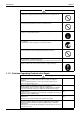
Introduction Si04-115 Caution Do not repair the electrical components with wet hands. Working on the equipment with wet hands can cause an electrical shock. Do not clean the air conditioner by splashing water. Washing the unit with water can cause an electrical shock. Be sure to provide the grounding when repairing the equipment in a humid or wet place, to avoid electrical shocks. Be sure to turn off the power switch and unplug the power cable when cleaning the equipment.
Si04-115 Introduction Warning Be sure to use the specified cable to connect between the indoor and outdoor units. Make the connections securely and route the cable properly so that there is no force pulling the cable at the connection terminals. Improper connections can cause excessive heat generation or fire. When connecting the cable between the indoor and outdoor units, make sure that the terminal cover does not lift off or dismount because of the cable.
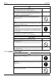
Introduction Si04-115 Caution Check to see if the parts and wires are mounted and connected properly, and if the connections at the soldered or crimped terminals are secure. Improper installation and connections can cause excessive heat generation, fire or an electrical shock. If the installation platform or frame has corroded, replace it. Corroded installation platform or frame can cause the unit to fall, resulting in injury. Check the grounding, and repair it if the equipment is not properly grounded.
Si04-115 Part 1 List of Function 1. Functions.................................................................................................2 1.1 Indoor Unit and Outdoor Unit ...................................................................
Functions Si04-115 1.
Si04-115 Part 2 Specification 1. Specifications ..........................................................................................4 1.1 Cooling Only.............................................................................................4 1.2 Heat Pump ...............................................................................................
Specifications Si04-115 1. Specifications 1.1 Cooling Only 220 - 230 - 240V, 50Hz 220 - 230V, 60Hz Model Indoor Units Outdoor Units Capacity Rated (Min.~Max.) Moisture Removal Running Current (Rated) Power Consumption Rated (Min.~Max.
Si04-115 Specifications 220 - 230 - 240V, 50Hz Model Indoor Units Outdoor Units Capacity Rated (Min.~Max.) Moisture Removal Running Current (Rated) Power Consumption Rated (Min.~Max.
Specifications Si04-115 220V, 60Hz Models Indoor Units Outdoor Units Capacity (Min.~Max.) Moisture Removal Running Current (Min.~Max.) Power Consumption (Min.~Max.) Power Factor (Min.~Max.) COP (Min.~Max.) EER (Min.~Max.
Si04-115 Specifications 230V, 50Hz Models Indoor Units Outdoor Units Capacity Rated (Min.~Max.) Moisture Removal Running Current (Rated) Power Consumption Rated (Min.~Max.
Specifications 1.2 Si04-115 Heat Pump 220-230-240V, 50Hz / 220-230V, 60Hz Indoor Units Models FTX25JVEA9 RX25JVEA9 Outdoor Units Capacity Rated (Min.~Max.) Moisture Removal Running Current (Rated) Power Consumption Rated (Min.~Max.
Si04-115 Specifications 220V, 60Hz Indoor Units Models FTX25JVET9 RX25JVET9 Outdoor Units Capacity (Min.~Max.) Moisture Removal Running Current (Min.~Max.) Power Consumption (Min.~Max.) Power Factor (Min.~Max.) COP (Min.~Max.) EER (Min.~Max.
Specifications Si04-115 230V, 50Hz Indoor Units Models FTX25JAV1NB RX25JV1NB9 Outdoor Units Capacity Rated (Min.~Max.) Moisture Removal Running Current (Rated) Power Consumption Rated (Min.~Max.
Si04-115 Part 3 Printed Circuit Board Connector Wiring Diagram 1. Printed Circuit Board Connector Wiring Diagram and Name ................12 1.1 FTK25/35J Series, FTX25/35J Series....................................................12 1.2 RK25/35J Series, RX25/35J Series .......................................................
Printed Circuit Board Connector Wiring Diagram and Name Si04-115 1. Printed Circuit Board Connector Wiring Diagram and Name 1.
Si04-115 Printed Circuit Board Connector Wiring Diagram and Name Control PCB (1) Signal receive P C B (2) Control P C B (1) S1 S27 GRN YLW GRN LED1 LED2 LED3 SW7 12V check Jumper S7 ground Intelligent eye sensor P C B (3) JA JB JC S6 5V check Jumper S36 S21 Printed Circuit Board Connector Wiring Diagram S32 S26 S35 (R1895) 13
Printed Circuit Board Connector Wiring Diagram and Name Si04-115 P.C.B (1) (Control P.C.
Si04-115 1.
Printed Circuit Board Connector Wiring Diagram and Name Si04-115 P.C.
Si04-115 Part 4 Main Function 1. General Functionality.......................................................................................18 1.1 1.2 1.3 1.4 1.5 1.6 1.7 1.8 1.9 1.10 1.11 1.12 1.13 1.14 1.15 1.16 1.17 1.18 1.19 Main Function Functions of Thermistors........................................................................18 Operating Modes....................................................................................20 Frequency Principle.............................................
General Functionality Si04-115 1. General Functionality 1.1 Functions of Thermistors The thermistors on the drawing below are used to control the system. This control secures a proper cooling and prevents problems of the unit: Location of thermistors OUTDOOR UNIT R2T R1T M INDOOR UNIT R1T M R2T FIELD PIPING FIELD PIPING COOLING HEATING Frequency control (R1899) The following table shows the thermistors that control the frequency: Controls Symbol Freeze-up prevention. Refer to page 19.
Si04-115 General Functionality Frequency controlled functions The following table shows the different functions, which are controlled by decreasing or increasing the frequency: Function Sensor Thermistor Why? How? Low outdoor temperatur e control outdoor ambient thermistor (R1T) To avoid condensation in cooling mode. By setting a Toutdoor ambient < high frequency 18°C limit.
General Functionality 1.2 Si04-115 Operating Modes Modes There are two operating modes: " normal operating mode " forced operating mode. Overview The following table shows the different control modes of the Split inverter room air conditioners: Mode Normal operating mode Item Auto (Heat pump only) Cooling Dry keep Heating (Including Automatic defrost) Fan (for Cooling only) Note: Test Operation Stop mode: " Pre-heat operation. Refer to “Pre-heat operation”.
Si04-115 1.3 General Functionality Frequency Principle Main control parameters Additional control parameters Inverter principle The compressor is frequency-controlled during normal operation. The target frequency is set by the following 2 parameters coming from the operating indoor unit: " the load condition of the operating indoor unit " the difference between the room temperature and the set temperature.
General Functionality Inverter features Si04-115 The inverter provides the following features: " The regulating capacity can be changed according to the changes in the outside temperature and cooling/heating load. " Quick heating and quick cooling The compressor rotational speed is increased when starting the heating (or cooling). This enables a quick set temperature.
Si04-115 1.4 General Functionality Defrost Control Principle Defrost control is carried out by reversing the cycle from heating to cooling.
General Functionality 1.5 Si04-115 Forced Operation Mode Forced mode Item Conditions Start Adjustment Reset " " " " " Forced cooling not in the 3-minute stand-by mode normal operation mode outdoor unit off no malfunction in the outdoor unit forced mode: cooling mode. 1. Keep pushing the operation switch of the indoor unit for 5 to 10 seconds. 2. Change the remote controller setting to a cooling test operation.
Si04-115 1.6 General Functionality Wide-angle Flaps, Diffuser, Louveres and Autoswing Outline of the action It can be commanded for J type by means of a user setting to select either any one desired position among the five-step directions of air flow adjusted on a remote controller, or Autoswing.
General Functionality 1.7 Si04-115 Fan Speed Control for Indoor Units Control mode The airflow rate can be automatically controlled depending on the difference between the set temperature and the room temperature. This is done through phase control and Hall IC control. For more information about Hall IC, refer to ‘Hall IC check (A6)’ on page 68. Phase steps Phase control and fan speed control contains 8 steps: LLL, LL, L, ML, M, HM, H and HH.
Si04-115 1.8 General Functionality Fan Speed Control for Outdoor Units Control The following drawing explains the fan speed control: ON C For ambient temperature between ˚C. OFF B˚C A˚C outdoor heat exchanger temperature (R1910) Fan off delay When the compressor turns off and T[outdoor ambient] > D°C, the outdoor fan stays running at the same speed for E seconds.
General Functionality 1.9 Si04-115 General Functions Pre-heat operation When the equipment has stopped and t[outside] < 11.5°C, the compressor is warmed-up by passing a single-phase (U, V phase) current through the compressor motor to speed up the start. The power consumption is 30-40W. Outside temperature 13.5˚C warm-up control for compressor 11.
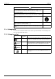
Si04-115 General Functionality " The frequency command for every zone is stated below. (Please note that an operation will not carry out in the commanded frequency sometimes in case a protection control like a freeze-protection etc. will be actuated.) Room temperature Command frequency Room temp. zone Room temp. < 18°C A J type (25 / 35) 0 / 0Hz except A A 34 / 34Hz 0 / 0Hz B D 34 / 34Hz 40 / 40Hz E F 42 / 42Hz 42 / 42Hz Room temp. ≥ 18°C 3.
General Functionality Si04-115 1.10 Intelligent Eye Outline The function that detects existence of humans in the air-conditioned room and reduces the capacity when no humans are available in the room in order to save electricity by means of a human motion sensor. Processing 1. Detection method by human motion sensor sampling (20msec) Sensor output 1sec If the sensor detects the outputs 10 times/sec. or more, it judges humans are available.
Si04-115 General Functionality conditions to conduct thermostat-off depending on the room temperature. In or after this forty minutes, if the sensor detects human motion detection signal, it turns on “Human detection LED” and let the set temperature and the fan speed return to the original set point, keeping a normal operation. Others " The dry operation can’t command the setting temperature with a remote controller, but internally the set temperature is shifted by 1°C.
General Functionality Si04-115 1.11 Good Sleep Cooling Control Outline The function to create deep sleeping and to offer good sleep by altering the set temperatures in certain intervals to give temperature variation to a living space based on “1/f temperature fluctuation” principle, in case of going to bed while air conditioner keeps operating in cooling mode. Processing [Unit: min] one cycle 20 Set temp.
Si04-115 General Functionality 1.12 Automatic Operation The unit automatically switches the operation mode to cooling or heating to maintain the room temperature at the main unit setting temperature. Detailed explanation of the function 1. Remote controller setting temperature is set as automatic cooling / heating setting temperature (18 to 30°C). 2. Main unit setting temperature equals remote controller setting temperature plus correction value (correction value / cooling: 0 deg, heating: 2 deg.). 3.
General Functionality Si04-115 1.13 Input Current Control Outline The frequency control will be carried out so that the input current will not exceed the rated value in the zone which is divided by the input current detected with CT as the figure below shows. Compressor stops. Stop zone I4 I4 = 10A Step down zone I3 Steady zone Iα = 1A I3 - Iα Input current detected with CT: I IN Return zone (R1919) " I4, I3, I3-Iα are included in the stop zone, step down, steady zone, respectively. Processing 1.
Si04-115 General Functionality 1.14 Freeze Protection Function in Cooling Outline During Cooling/Dry operation, when the heat exchanger’s temperature falls down excessively, the capacity supply will be reduced (frequency step down) so as to prevent freeze of the heat exchanger and the creation of dew on a rotor caused by a excessive capacity supply to the indoor unit. Processing at the rise of heat exchanger temp. Return from stop.
General Functionality Si04-115 1.15 Peak-Cut Control Function Outline In a heating operation, there will be anxiety that a head pressure excessively increases and exceeds the permissible limit in an over load conditions.
Si04-115 General Functionality 1.16 Four-Way Valve Function Compensation Outline When the initial start of compressors is required after power is on or at operation mode’s alteration (Cooling/Dry ↔ Heating) that the a switch-over of a four-way valve takes place, it secures the necessary differential pressure by restricting the operation frequency in the lower limit in a certain period, and the switch-over action is ensured. Processing 1.
General Functionality Si04-115 1.17 Compressor Protection Function Outline An refrigeration oil level descent and progression of the dilution which will arise at operation of the compressors will be avoided by controlling the upper limit of frequency at the edge of compressor’s changeover from OFF to ON as follows. Processing Compressor operation frequency F CG3 F CG2 F CG1 T CG0 T CG1 T CG2 T CG3 Power ON time (R1907) 1. A choice of a constant based on the starting conditions.
Si04-115 General Functionality 1.18 Wet Operation Protection Outline The lower limit of output frequency is limited in two steps in accordance with outdoor conditions in order to secure the reliability of compressor (suction dryness and differential pressure). Processing 1. at the first step During operation of compressors. Outdoor temperature ≤ DOA1CG " If and are under the simultaneous condition with AND, the lower limit of frequency in this function is set at FCG7. Compressors stop.
General Functionality Si04-115 1.19 Dew Condensation Sweating Prevention Function Outline During Cooling/Dry operation, when the heat exchanger’s temperature falls down excessively, the capacity supply will be reduced (frequency step down) so as to prevent dew formation around a discharge grille caused by a excessive capacity supply to an indoor unit. Processing 1. Conditions of beginning/ending for this function. Operation mode is in Cooling/Dry. Compressors operate.
Si04-115 Part 5 System Configuration 1. Instruction..............................................................................................42 1.1 FTK25 / 35J, FTX25 / 35J ......................................................................
Instruction Si04-115 1. Instruction 1.1 FTK25 / 35J, FTX25 / 35J Safety Precautions ■ Read the following warnings and cautions carefully before operating the system and use it correctly. ■ This manual classifies the precautions to the user into two categories on the right. Be sure to follow all as they are all important to ensure safety. ■ After reading this manual, keep it in a place easily accessible to the user for future reference.
Si04-115 Instruction Installation WARNING Do not attempt to install the air conditioner by yourself. Consult the service shop or a qualified technician. Incorrect work will result in water leakage, electric shocks or fire. For installation, consult the service shop where you bought the unit or a qualified technician. The air conditioner must be earthed. Incomplete earthing may result in electric shocks. Do not connect the earth line to a gas pipe, water pipe, lightening rod, or a telephone earth line .
Instruction Si04-115 Names of Parts Indoor unit Air purifying filter Air purifying filters are attached to the inside of the air filters. Front grille Air inlet Grille tab Air outlet Louvre (vertical blades) The louvre is inside of the air outlet. (See page 50 “Adjusting the Air Flow Direction”.) Flap (horizontal blade) Indicator lamps ON/OFF button TIMER lamp (orange) (See page 48.) (See page 51 “Timer Operation”.) (See page 50 “Adjusting the Air Flow Direction”.
Si04-115 Instruction Names of Parts Outside air temperature sensor Outdoor unit It senses the ambient temperature around the unit. Air inlet (Back and side) Refrigerant piping and inter-unit cable Drain hose Air outlet Earth terminal It is inside of this part. Appearance of the outdoor unit may differ with some models. Remote controller Open the cover. Display Transmitter It displays the current settings.
Instruction Si04-115 Preparation Before Operation n Operating the remote controller Remote controller l To use the remote controller, aim the transmitter at the indoor n Setting the batteries unit. If there is anything to block signals between the unit and the remote controller, such as a curtain, the unit will not operate. l Do not drop the remote controller. Do not get it wet. l The maximum distance for communication is about 7 m.
Si04-115 Instruction Preparation Before Operation Indoor unit n Setting the air purifying 1 filters Open the front grille . l Hold the grille by the tabs on the two sides and lift it until n Setting 1 the clock Press . it stops with a click. (about 60˚) Display AM Pull out the air filters. l Push upwards the tab at 2 blinks. Press to set the clock to the present time. TIMER the center of each air filter, then pull it down. Display 2 is displayed.
Instruction Si04-115 AUTO • DRY • COOL • HEAT • FAN Operation To change the air flow rate setting: Press FAN . AUTO or HEAT or COOL or FAN mode DRY mode MODE Press and select a mode. The air flow rate setting is not variable. Display 1 Five levels of air flow rate setting from " " to " "plus " " are available. Display The air conditioner operates with the settings of your choice. From the next time on, the air conditioner will operate with the same settings.
Si04-115 Instruction POWERFUL Operation POWERFUL operation quickly maximizes the cooling (heating) effect in any operation mode. You can get the maximum capacity with a touch of a button. ● Pressing the (POWERFUL) button during operation starts POWERFUL operation. ● POWERFUL operation ends in 20 minutes. Then the system automatically operates again with the settings which were used before POWERFUL operation. ● During you use POWERFUL operation, the other function will not go on. Press .
Instruction Si04-115 Adjusting the Air Flow Direction You can adjust the air flow direction to increase your comfort. Adjusting the louvre Adjusting the horizontal blade (flap) Press SWING while the air conditioner is operating. l Every time the button is pressed, " " appears or disappears. ....... The flap automatically swings up and down. ....... To stop the flap at an Hold the knob and move the louvre. (You will find a knob on the left-side and the right-side blades.
Si04-115 Instruction Timer Operation OFF TIMER operation ● Check that the clock is correct. If not, set the clock to the present time. (See page 46.) 1 Press OFF while the air conditioner ON TIMER operation ● Check that the clock is correct. If not, set the clock to the present time (See page 46). 1 Press ON while the air conditioner is not operating. Display Timer functions are useful for automatically switching the air conditioner on or off at night or in the morning.
Instruction Si04-115 Good Sleep Cooling Operation (G-SLEEP) •The "Good Sleep Cooling Operation" makes the 1/f Fluctuating Temperature. It brings you comfortable sleep as it prevents from getting chilied. 1 Press -SLEEP in cooling operation. n To change the temperature setting. (See page 48.) n To change the air flow rate setting. (See page 48.) n To change the air flow direction setting. (See page 50.) n To cancel the "Good Sleep Cooling Operation ", press → Back to the normal cooling opration.
Si04-115 Instruction Intelligent Eye “Intelligent Eye” is the infrared sensor which detecs the human movement. 1 SENSOR Press While the air conditioner is operating. (The Sensor lamp lights up.) ■ Adjusting the angle of the Intelligent-eye sensor • You can adjust the angle of the Intelligent-eye sensor to remove the detection area. (Adjustable angle: 15˚ to right and left of centre) ■ To cancel the “Intelligent Eye”, press SENSOR . (The Sensor lamp goes off.) [EX.
Instruction Si04-115 Care and Cleaning CAUTION Before cleaning, be sure to stop the operation and turn the breaker OFF. Cleaning the air filters (It is recommended to clean them every two weeks.) 1 Open the front grille. l Hold the grille by the tabs on the two sides and lift it unitl it stops with a click. (about 60˚) 2 Pull out the air filters. l Push a little upwards the tab Cleaning the indoor and outdoor units and the remote controller l Wipe them with dry soft cloth.
Si04-115 Instruction Care and Cleaning Check Cleaning the front grille You may remove the front grille for cleaning. CAUTION l When removing or attaching the front grille, use a robust and stable stool and watch your steps carefully. l When removing or attaching the front grille, support the grille securely with hand to prevent it from falling.
Instruction Si04-115 Trouble Shooting l These cases are not troubles. The following cases are not air conditioner troubles but have some reasons. You may just continue using it. Case Operation does not start soon. l When ON/OFF button was pressed soon after operation was stopped. l When the mode was reselected. Hot air does not flow out soon after the start of heating operation. The heating operation stops suddenly and a flowing sound is heard. The outdoor unit emits water or steam.
Si04-115 Instruction Trouble Shooting l Check again Please check again before calling a repair person. Case The air conditioner does not operate . (OPERATION lamp is off) Check l Hasn't a breaker turned OFF or a fuse blown? l Isn't it a power failure? l Are batteries set in the remote controller? l Is the address switch in the remote controller set correctly? (See page 39 "Preparation Before Operation".) l Is the timer setting correct? Cooling or Heating effect is poor .
Instruction Si04-115 Trouble Shooting ● Call the service shop immediately. WARNING ■ When an abnormality (such as a burning smell) occurs, stop operation and turn the breaker OFF. Continued operation in an abnormal condition may result in troubles, electric shocks or fire. Consult the service shop where you bought the air conditioner. ■ Do not attempt to repair or modify the air conditioner by yourself. Incorrect work may result in electric shocks or fire.
Si04-115 Instruction Trouble Shooting ● Fault diagnosis FAULT DIAGNOSIS BY REMOTE CONTROLLER IN THE EVENT OF AN ABNORMALITY, THE RELEVANT ABNORMALITY CODE APPEARS FLASHING IN THE REMOTE CONTROLLER'S TEMPERATURE DISPLAY.
Instruction 60 Si04-115 System Configuration
Si04-115 Part 6 Service Diagnosis 1. Caution for Diagnosis............................................................................62 1.1 Troubleshooting with The Operation Lamp ............................................62 2. Problem Symptoms and Measures .......................................................63 3. Service Check Function ........................................................................64 3.1 ARC423 Series.........................................................................
Caution for Diagnosis Si04-115 1. Caution for Diagnosis 1.1 Troubleshooting with The Operation Lamp The Operation lamp flashes when any of the following errors is detected. 1. When a protection device of the indoor or outdoor unit is activated or when the thermistor malfunctions, disabling equipment operation. 2. When a signal transmission error occurs between the indoor and outdoor units. In either case, conduct the diagnostic procedure described in the following pages.
Si04-115 Problem Symptoms and Measures 2. Problem Symptoms and Measures Problem Symptom Check Item Details of Measure None of The Units Operates. Check the power supply. Check to make sure that the rated voltage is supplied. Check the type of the indoor units. Check to make sure that the indoor unit type is compatible with the outdoor unit.
Service Check Function Si04-115 3. Service Check Function 3.1 ARC423 Series In the ARC423A series, the temperature display sections on the main unit indicate corresponding codes. 1. When the timer cancel button is held down for 5 seconds, a “00” indication flashes on the temperature display section. < Cover in open position > Open the cover. Display Transmitter It displays the current settings. (In this illustration, each section is shown with all its displays ON for the purpose of explanation.
Si04-115 Code Indication on The Remote Controller 4. Code Indication on The Remote Controller 4.
Trouble shooting Si04-115 5. Trouble shooting 5.1 Faulty PCB Remote Controller Display A1 Indoor unit LED Display Method of Malfunction Detection Evaluation of zero-cross detection of power supply by indoor unit. Malfunction Decision Conditions " When there is no zero-cross detection in approximately 10 continuous seconds. " When the information saved in E2PROM cannot be read. Supposed Causes " Faulty indoor unit PCB Troubleshooting " Replace the indoor unit PCB.
Si04-115 5.2 Trouble shooting Operation Shutdown Due to High-Pressure Control or Freeze-Up Protection (Thermistor Activation) Remote Controller Display A5 Indoor unit LED Display Method of Malfunction Detection " High pressure control Malfunction Decision Conditions " High pressure control Supposed Causes " " " " " During heating operations, the temperature detected by the indoor heat exchanger thermistor is used for the high pressure control (stop, outdoor fan stop, etc.
Trouble shooting 5.3 Si04-115 Operation Halt Due to Fan Motor (AC Motor) or Related Abnormality Remote Controller Display A6 Indoor unit LED Display Method of Malfunction Detection The rotation speed detected by the hall IC during fan motor operation is used to determine abnormal fan motor operation. Malfunction Decision Conditions When the detected rotation speed is less than 50% of the HH tap under maximum fan motor rotation demand.
Si04-115 5.4 Trouble shooting Operation Halt Due to Detection of Thermistor or Related Abnormality C4, C9, CA Remote Controller Display Indoor unit LED Display Method of Malfunction Detection The temperatures detected by the thermistors are used to determine thermistor errors. Malfunction Decision Conditions When the thermistor input is more than 4.96 V or less than 0.04 V during compressor operation∗. ∗ (reference) When above about 212°C (less than 120 Ω) or below about -50°C (more than 1,860 kΩ).
Trouble shooting 5.5 Si04-115 Faulty Indoor Unit PCB Remote Controller Display ∗ Indoor unit LED Display Method of Malfunction Detection The proper program operation of the microcomputer is checked by the program. Malfunction Decision Conditions When the microcomputer program does not function properly. Supposed Causes " Microcomputer program is in abnormal condition due to an external factor. ∗Noise. ∗Momentary voltage drop. ∗Momentary power failure, etc. " Faulty indoor unit PCB.
Si04-115 5.6 Trouble shooting Faulty Indoor Unit PCB Remote Controller Display ∗ Indoor unit LED Display Method of Malfunction Detection The condition of the transmission circuit for indoor-outdoor signal transmission is detected. Malfunction Decision Conditions When the transmission circuit remains ON. Supposed Causes " Faulty indoor unit PCB Troubleshooting " Replace the indoor unit PCB.
Trouble shooting 5.7 Si04-115 Power Supply Abnormalities or Faulty Indoor Printed Circuit Boards Remote Controller Display ∗ or U4 Indoor unit LED Display Method of Malfunction Detection 1. The proper program operation of the microcomputer is checked by the program. 2. In indoor-outdoor signal communications, the indoor unit determines whether the outdoor unit receives signals properly by detecting signals transmitted by the outdoor unit to the indoor unit. Malfunction Decision Conditions 1.
Si04-115 5.8 Trouble shooting Signal Transmission Error (Between Indoor and Outdoor Units) Remote Controller Display U4 Indoor unit LED Display Method of Malfunction Detection The data received from the outdoor unit in indoor unit-outdoor unit signal transmission is checked whether it is normal. Malfunction Decision Conditions When the data sent from the outdoor unit cannot be received normally, or when the content of the data is abnormal. Supposed Causes " " " " " Faulty outdoor unit PCB.
Trouble shooting 5.9 Si04-115 Operation Halt Due to Detection of CT Error Remote Controller Display H8 Outdoor unit LED Display A5 Method of Malfunction Detection CT errors are detected using the compressor's operating frequency and the input current detected by the CT. Malfunction Decision Conditions When the compressor's operating frequency is more than 62 Hz and the CT input is less than 0.1 V. ∗ Inlet current 0.75 A " When a CT error is generated 4 times, the system shuts down.
Si04-115 Trouble shooting 5.10 Operation Halt Due to Thermistor Error or Disconnection Detection Remote Controller Display J3, J6, H9 Outdoor unit LED Display A5 Method of Malfunction Detection Thermistor errors are detected using thermistor input voltage to micro computer. (Thermistor errors are detected using the temperatures detected by the thermistors.) Malfunction Decision Conditions Supposed Causes When the thermistor input during compressor operation is more than 4.96 V or less than 0.04 V.
Trouble shooting Si04-115 5.11 Operation Halt Due to Compressor Startup Error Remote Controller Display E6 Outdoor unit LED Display A5 Method of Malfunction Detection Compressor startup errors are detected using input current detected by CT and compressor’s operation frequency. Malfunction Decision Conditions When the inlet current is over the setting value.
Si04-115 Trouble shooting 5.12 Output Overcurrent Remote Controller Display L5 Outdoor unit LED Display A5 Method of Malfunction Detection Detection of output overcurrent based on current flowing in Power transistor. (Inverter direct current part) Malfunction Decision Conditions When output overcurrent enters microcomputer from output overcurrent detection circuit. When error occurs 6 times, system shuts down.
Trouble shooting Troubleshooting Si04-115 ∗ Erroneous internal wiring can result in output overcurrent in some cases. If system stops due to output overcurrent after parts replacement that requires disconnection of wires, check wiring carefully Check No.3 Refer to P.85 Caution Be sure to turn off power switch before connect or disconnect connector, or parts damage may be occurred. Is stop valve fully open? Check No.4 Refer to P.87 Check No.12 Refer to P.90 Fully open stop valve.
Si04-115 Trouble shooting 5.13 Faulty Outdoor Unit PCB Remote Controller Display ∗ Outdoor unit LED Display A4 Method of Malfunction Detection The proper program operation of the microcomputer is checked by the program. Malfunction Decision Conditions When the microcomputer program does not function properly. Supposed Causes " Microcomputer program run-away due to an external factor. ∗Noise ∗Momentary voltage drop ∗Momentary power failure, etc. " Faulty outdoor unit PCB.
Trouble shooting Si04-115 5.14 Faulty Outdoor Unit PCB and Transmitting/Receiving Circuit Remote Controller Display ∗ Outdoor unit LED Display A3 Method of Malfunction Detection 1. The proper program operation of the microcomputer is checked by the program. 2. Signals transmitted from the outdoor unit to the indoor unit are received by the outdoor unit itself in indoor unit -outdoor unit signal transmission mode, and proper receiving of the signals by the indoor unit is checked.
Si04-115 Trouble shooting 5.15 Operation Halt Due to Detection of Input Over Current Remote Controller Display E8 Outdoor unit LED Display A5 Method of Malfunction Detection Input over current is checked using the input current detected by the CT during compressor operation. Malfunction Decision Conditions When the CT input remains above the value shown in the below table for 2.5 seconds during compressor operation. Table for constant Model Input current (A) RK(X)25, 35 Series 10.
Trouble shooting Troubleshooting Check No.3 Refer to P.85 Check No.4 Refer to P.87 Si04-115 ∗ Internal wiring errors can cause an input over current. If the equipment stops due to an input over current after the wires are disconnected and connected again for parts replacement, etc., check for wiring errors. Caution Be sure to turn off power switch before connect or disconnect connector, or parts damage may be occurred. Re-start the equipment, and measure the input current.
Si04-115 Trouble shooting 5.16 Interrupt due to OL Action Remote Controller Display E5 Outdoor unit LED Display A5 Method of Malfunction Detection " OL action detected by the opening of OL contact. Malfunction Decision Conditions Supposed Causes Service Diagnosis If an OL action signal has come to the microcomputer. " OL action detected twice, resulting in a shutdown of the system.
Trouble shooting Si04-115 Troubleshooting Caution Check No.17 Refer to P.92 Be sure to turn off power switch before connect or disconnect connector, or parts damage may be occurred. Check continuity between contacts using a tester. Is there continuity (with system shut down and compressor cool down)? NO Replace the OL. YES Check connection of the OL connector. Is the connector tight? NO Reconnect the OL connector. YES Check continuity of the OL harness.
Si04-115 Check 6. Check 6.1 How to Check 6.1.1 Power transistor check Capacitor voltage check Check No.3 1. Power transistor check Note: Check to make sure that the voltage between the terminal of Power transistor (+) and (-) is approx. 0 volt before checking power transistor. < Measuring method > Disconnect the compressor harness connector from the outdoor unit PCB. To disengage the connector, press the protrusion on the connector.
Check Si04-115 < Measuring positions > Take measurements at the power transistor (+) and (-) terminals in the same way as described in section 1. Set the multi-tester to DC and VOLTAGE RANGE before measurement. ∗ Since capacitor (+) and (-) are connected to power transistor (+) and (-), capacitor voltage can be measured at the power transistor (+) and (-) terminals.
Si04-115 Check 6.1.2 Power Transistor Output Check Check No.4 Measure the output current and voltage of the power transistor. Output Current Measurement Remove the front panel, and measure the current in the red, yellow and blue wire harness inside the compressor using a clamp meter. 1. Attach the clamp meter to the red, yellow and blue wire harness, and conduct forced cooling operation. 2. When the output frequency has stabilized, measure the output current of each phase. 3.
Check Si04-115 6.1.3 Thermistor Resistance Check Check No.5 Remove the connectors of the thermistors on the PCB, and measure the resistance of each thermistor using tester. The relationship between normal temperature and resistance is shown in the graph and the table below. Thermistor R25°C=20kΩ B=3950 88 Temperature (°C) -20 211.0 (kΩ) -15 -10 150 116.5 -5 0 88 67.2 5 10 51.9 40 15 20 31.8 25 25 30 20 16 35 40 13 10.6 45 50 8.7 7.
Si04-115 Check For the models whose thermistor is directly equipped on the printed circuit board; " Remove the signal receiver and the display printed circuit board (disconnect the connector too), and then measure ohm by an ohmmeter at the both ends. " Electric resistance cannot be precisely measured when a wire harness is connected directly to a printed circuit board instead of using a connector. When error display reappears, replace the PCB.
Check Si04-115 6.1.5 Rectifier Check Check No.11 There are several different terminal position patterns. Therefore, be sure to check the terminal marks. Negative (-) terminal of tester (positive ~ terminal (+ for digital tester) Positive (+) terminal of tester (negative + terminal (-) for digital tester) + ~ - ~ - ~ ∞ 0 Several KΩ to MΩ 0 or ∞ Several KΩ to MΩ ∞ 0 0 or ∞ Normal resistance Unacceptable resistance 6.1.6 Discharge Pressure Check Check No.
Si04-115 Check 6.1.7 Power Supply Waveforms Check Check No.13 Measure the power supply waveform between pins 1 and 3 on the terminal board, and check the waveform disturbance. " Check to see if the power supply waveform is a sine wave (Fig.1). " Check to see if there is waveform disturbance near the zero cross (sections circled in Fig.2) [Fig.1] [Fig.2] 6.1.8 Inverter Units Compressor/Refrigerant System Check Check No.
Check Si04-115 6.1.9 Hall IC Check Check No.16 1. Check the connector connection. 2. With the power ON, operation OFF, and the connector connected, check the following. ∗Output voltage of about 5 V between pins 1 and 3. ∗Generation of 3 pulses between pins 2 and 3 when the fan motor is operating. Failure of (1) $ faulty PCB $ Replace the PCB. Failure of (2) $ faulty hall IC $ Replace the fan motor. Both (1) and (2) result $ Replace the PCB. 6.1.10 Refrigerant System Check Check No.
Si04-115 Part 7 Removal Procedure 1. For FTK25J, FTK35J, FTX25J, FTX35J ...............................................94 1.1 1.2 1.3 1.4 1.5 1.6 1.7 Removal of Air Filter...............................................................................94 Removal of Front Grille ..........................................................................97 Removal of Horizontal Blade and Vertical Blade..................................100 Removal of Switch Box, PC Board and Swing Motor.........................
For FTK25J, FTK35J, FTX25J, FTX35J Si04-115 1. For FTK25J, FTK35J, FTX25J, FTX35J 1.1 Removal of Air Filter Procedure Warning Be sure to wait 10 minutes or more after turning off all power supplies before disassembling work.. Step Procedure Points 1. External features (Illustrations show D series.) " If ON/OFF button is kept pushing for 5 seconds, a forced cooling operation will be carried out for approx. 15 minutes. 2.
Si04-115 Step Procedure 3. Opening and shutting front panel 1 Hook a finger onto the projection part provided on the both sides of the unit’s panel and open up the panel to the position higher than it will stop. 2 For FTK25J, FTK35J, FTX25J, FTX35J Points Support the front panel by one hand, while remove the rotation axis at the upper center by the other hand. " And pull out the front panel forward to remove. Remove front panel from the unit.
For FTK25J, FTK35J, FTX25J, FTX35J Step 3 96 Si04-115 Procedure Points When restoring the air filter, make sure that the projection parts on the panel are in the guide groove, and then shut the panel.
Si04-115 1.2 For FTK25J, FTK35J, FTX25J, FTX35J Removal of Front Grille Procedure Warning Be sure to wait 10 minutes or more after turning off all power supplies before disassembling work.. Step Procedure Points 1. Opening and closing of service cover 1 Remove a service cover mounting screw. Open service cover upward " A switch for field setting is not provided in particular.
For FTK25J, FTK35J, FTX25J, FTX35J Step Procedure 2. Removal of front grille assembly. 1 Remove the two screws, in the right and the left, which fix the main body with the front grille. 2 98 Si04-115 Disengage the two hooks on the upper part. In case that the hooks are not pressed from above, remove the front panel and then remove the grille while pushing the hook through a clearance between the front grille and the heat exchanger.
Si04-115 Step 3 For FTK25J, FTK35J, FTX25J, FTX35J Procedure The front grille can be removed in a manner to pull out the upper part forward and lift up the lower part. Removal Procedure Points " When restoring the grille, Make sure whether each hook is set as it was.
For FTK25J, FTK35J, FTX25J, FTX35J 1.3 Removal of Horizontal Blade and Vertical Blade Procedure Warning Be sure to wait 10 minutes or more after turning off all power supplies before disassembling work. Step Procedure 1. Remove horizontal blade. 1 Lift horizontal blade to open position. 2 Disengage horizontal blade from blade retaining section. 3 Bend blade slightly and remove it from the unit.
Si04-115 Step For FTK25J, FTK35J, FTX25J, FTX35J Procedure Points " For restoring. 1. Since the key pattern hook is provided on the left side, insert the edge of the blade to the tip while rotating it. 2. Restore the two fixed parts of the horizontal blade onto the hook. 2. Removal of vertical blade 1 Disengage the vertical blade’s joint from the fixed plate. 2 Remove the blade forward. Removal Procedure " Five vertical blades are integrated with the joint rod.
For FTK25J, FTK35J, FTX25J, FTX35J 1.4 Si04-115 Removal of Switch Box, PC Board and Swing Motor Procedure Warning Be sure to wait 10 minutes or more after turning off all power supplies before disassembling work. Step Procedure Points " Remove front grill. 1. Remove switch box. 1 Disconnect the connection wires. 2 Disconnect connectors (S1 and S7) of fan motor. " Pay attention to the direction 3 4 102 Disconnect one connector (S6) of swing motor. Remove heat exchanger thermistor.
Si04-115 Step 5 6 For FTK25J, FTK35J, FTX25J, FTX35J Procedure Remove a screw on the terminal strip. Points " The switch box can be removed instead of disengaging the terminal strip. Remove a screw on the switch box.
For FTK25J, FTK35J, FTX25J, FTX35J Step 7 104 Si04-115 Procedure Pull up the switch box forward to remove. Points " A hook is provided on the behind.
Si04-115 Step For FTK25J, FTK35J, FTX25J, FTX35J Procedure Points 2. Removal of printed circuit board 1 Remove the shelter. 2 Disengage the front plate of the switch box. Disengage the knobs by pushing the two hooks at the top and the bottom. 3 Sliding to the left, the front part of the switch box can be removed.
For FTK25J, FTK35J, FTX25J, FTX35J Step Procedure 4 Disengage the four knobs on the back of the display printed circuit board. 5 Display printed circuit board.
Si04-115 Step 6 For FTK25J, FTK35J, FTX25J, FTX35J Procedure Control printed circuit board. Points " The control printed circuit board is integrated with the power supply printed circuit board. 3. Remove swing motor assembly. 1 To remove swing motor assembly, remove two screws. (Manual adjusting for the vertical blades.) " Provide a supporter so that the joint link will not drop off, in case the horizontal blade assembly is removed.
For FTK25J, FTK35J, FTX25J, FTX35J 1.5 Si04-115 Removal of Heat Exchanger Procedure Warning Be sure to wait 10 minutes or more after turning off all power supplies before disassembling work. Step Procedure Points " Conduct pump-down operation. " Remove the installation frame from the mounting plate. 1 Remove the drain hose. Make curing so that the residual drain water will not leak out. Warning! If gas leaks, repair the leak location, then connect all refrigerant from the unit.
Si04-115 Step Procedure 4 Disengage the hooks of the pipe retainer on the back. 5 Pull auxiliary pipe forward to an angle of 10 to 20 degrees. 6 For FTK25J, FTK35J, FTX25J, FTX35J Points " Be careful to prevent pipe deformation. Disengage hooks located right and left side, and pull heat exchanger forward. The hooks are symmetrically placed in the right and the left. " Lifting the heat-exchanger slightly upward to the right, the left hook comes to be disengaged easily.
For FTK25J, FTK35J, FTX25J, FTX35J Step 7 110 Si04-115 Procedure Lift and remove heat exchanger. Points Caution! When removing or reinstalling heat exchanger, be sure to wear protective gloves or wrap heat exchanger with cloths. (Fins can cut fingers.
Si04-115 1.6 For FTK25J, FTK35J, FTX25J, FTX35J Install of Drain Plug Procedure Warning Be sure to wait 10 minutes or more after turning off all power supplies before disassembling work. Step 1 Disconnect drain hose. Procedure Points " The drain pan is integrated with the bottom plate. 2 Pull out the drain plug in the left on the drain pan by hand. 3 Insert the drain hose, " Push it into the inner part firmly. 4 Push the drain plug into the right by Allen wrench.
For FTK25J, FTK35J, FTX25J, FTX35J 1.7 Si04-115 Removal of Fan Rotor and Motor Procedure Warning Be sure to wait 10 minutes or more after turning off all power supplies before disassembling work. Step Procedure Points " Remove heat exchanger. 1 112 To remove right side panel, remove three screws.
Si04-115 Step For FTK25J, FTK35J, FTX25J, FTX35J Procedure 2 Disengage hook. 3 Loosen the hexagon head set screw on the fan rotor.
For FTK25J, FTK35J, FTX25J, FTX35J Step Procedure 4 Remove the motor and fan rotor. 5 Remove a screw on the left side panel.
Si04-115 Step For FTK25J, FTK35J, FTX25J, FTX35J Procedure 6 Disengage a hook from the backward. 7 Since the fan bearing is made of rubber, push it strongly off from the inside. The bearing can be removed just as the left-side plate is attached with.
For RK25J, RK35J, RX25J, RX35J Si04-115 2. For RK25J, RK35J, RX25J, RX35J 2.1 Removal of External Casing Procedure Warning Be sure to turn off all power supplies at least 10 min. before disassembling work. Step 1 Procedure Points The stop valve cover can be removed when the fixed screw is removed. " As three hooks are provided, slide the cover downward to remove.
Si04-115 Step For RK25J, RK35J, RX25J, RX35J Procedure 2 The top plate and the front plate are constructed in a monoblock. Remove the three screws on the right side and the two screws on the front plate. 3 Remove the three screws on the left side. 4 Remove the one fixed screw in the rear of the top plate. Once lift the top plate and then remove it forward. Removal Procedure Points " The left side plate and the bell mouth can be removed all at once.
For RK25J, RK35J, RX25J, RX35J Step 5 Si04-115 Procedure The front plate and the left side plate can be removed when the one fixed screw is removed. Points " Sectional view at the front. Top plate The edge of the top plate gets into this groove.
Si04-115 2.2 For RK25J, RK35J, RX25J, RX35J Removal of Bell mouth and Left Side Plate Procedure Warning Be sure to turn off all power supplies at least 10 min. before disassembling work. Step 1 The bell mouth is attached to the front plate with two screws and four hooks. 2 Remove the two screws and undo the four hooks to release the bell mouth. Removal Procedure Procedure Points " Remove the bell mouth from the front plate after removing the two screws which are set below.
For RK25J, RK35J, RX25J, RX35J 2.3 Si04-115 Removal of PC Board and Switch Box Procedure Warning Be sure to turn off all power supplies at least 10 min. before disassembling work. Step 1. Remove the shelter. 1 Undo the five hooks and remove the shelter. Procedure Points " The shelter has five hooks. " Be sure to avoid forgetting to restore the shelter and to avoid loosing or damaging it. 2. Remove the printed circuit board. 1 Disconnect the ground wire.
Si04-115 Step For RK25J, RK35J, RX25J, RX35J Procedure 2 Remove the four screws fixing the printed circuit board. 3 Disconnect the wire harness. 4 Disconnect the two connectors of the reactor.
For RK25J, RK35J, RX25J, RX35J Step 5 6 122 Si04-115 Procedure Undo the eight hooks and the printed circuit board can be disengaged. Points " The printed circuit board has eight hooks. Disconnect the three wires from the printed circuit board.
Si04-115 Step 7 For RK25J, RK35J, RX25J, RX35J Procedure Points The printed circuit board can completely be released. 3. Remove the switch box. 1 Remove the two screws fixing the switch box.
For RK25J, RK35J, RX25J, RX35J Step 2 Si04-115 Procedure Points Lift and remove the switch box. 4. Remove the molded interconnect device (MID). 1 Remove the one screw fixing the MID.
Si04-115 Step 2 For RK25J, RK35J, RX25J, RX35J Procedure Points Slide the MID upward and release.
For RK25J, RK35J, RX25J, RX35J 2.4 Removal of Propeller Fan and Fan Motor Procedure Warning Be sure to turn off all power supplies at least 10 min. before disassembling work. Step Procedure " Disconnect the fan motor connector S70. 1 Release the lead-wires of the fan motor from the groove of the switch box. 2 3 126 Si04-115 The propeller fan can be removed when the washer faced nut (M8) is removed. Points " Remove the external plates and the drip proof cover protecting the electric parts.
Si04-115 Step 4 For RK25J, RK35J, RX25J, RX35J Procedure Points Remove the fan motor.
For RK25J, RK35J, RX25J, RX35J 2.5 Si04-115 Removal of Compressor Noise Absorption Pad Procedure Warning Be sure to turn off all power supplies at least 10 min. before disassembling work. Step Procedure Points 1. To remove the right side plate. 1 Remove the three screws for removing the right side plate. 2 Lift the right side plate to disengage the hooks. 2. To remove the noise absorber 1 Untie the string fixing the body of the compressor noise absorption pad.
Si04-115 Step For RK25J, RK35J, RX25J, RX35J Procedure Points 2 Pull out the body of the noise absorption pad. 3 Pull out the top pad of the noise absorption (a). " Since the slit prepared for Pull out the body of the noise absorption pad (b). " When restoring, the noise 4 Removal Procedure the piping on the noise absorption pad is torn easily, remove the pad carefully. absorption pad should pass the internal side of the piping.
For RK25J, RK35J, RX25J, RX35J 2.6 Removal of Partition Plate and Reactor Procedure Warning Be sure to turn off all power supplies at least 10 min. before disassembling work. Step 1. To remove the partition plate. 1 Disengage the lead wires from the wire clip. 2 Remove the two screws fixing the partition plate. 3 Pull the partition plate upward to remove.
Si04-115 Step 4 For RK25J, RK35J, RX25J, RX35J Procedure Points When restoring the partition plate, put the hook into the bottom frame. 2. To remove the reactor 1 The reactor can be removed by removing the fixed screw.
For RK25J, RK35J, RX25J, RX35J 2.7 Si04-115 Removal of Four-way Valve Procedure Warning Be sure to turn off all power supplies at least 10 min. before disassembling work. Step Procedure Points 1. To remove the parts around the four-way valve. 1 Remove the terminal cover, the lead wires of the compressor and the partition plate so as not to be burnt out by a gas brazing machine. 2 Remove the thermister for the heat exchanger.
Si04-115 Step For RK25J, RK35J, RX25J, RX35J Procedure Points " Begin your work after recognizing complete empty of refrigerant in the refrigerant circuit. 4 Provide a protective sheet or a steel plate so that the brazing flame can’t influence the circumstance around the four-way valve. 5 Heat up the four portions of brazing parts on the four-way valve. Remove the fourway valve in the order of (a),(b),(c),(d).
For RK25J, RK35J, RX25J, RX35J 2.8 Removal of Compressor Procedure Warning Be sure to turn off all power supplies at least 10 min. before disassembling work. Step 1. To Remove the Parts Around the Compressor. 1 Remove the terminal cover, the lead wires of the compressor and the partition plate so as not to be burnt out by a gas brazing machine. 134 Si04-115 Procedure Points " Be careful so as not to burn the compressor terminals or the name plate.
Si04-115 Step 2 3 For RK25J, RK35J, RX25J, RX35J Procedure Points The compressor’s mounting nut to be removed is one piece. Remove the nut by means of an open-end wrench. " Begin your work after recognizing complete empty of refrigerant in the refrigerant circuit. " Be sure to apply nitrogen’s permutation when heating up the brazing part. 1 Remove the brazing part on the compressor discharge side. 2 Heat up the brazing part on the compressor suction part and then remove it.
For RK25J, RK35J, RX25J, RX35J 136 Si04-115 Removal Procedure
Si04-115 Part 8 Others 1. Others .................................................................................................138 1.1 Explanation...........................................................................................
Others Si04-115 1. Others 1.1 Explanation 1.1.1 Test Run from the Remote Controller (For Heat Pump Model Only) Trial Operation and Testing 1. Measure the supply voltage and make sure that it falls in the specified range. 2. Trial operation should be carried out in either cooling or heating mode. For Heat pump For Cooling operation in case of low ambient temperature In cooling mode, select the lowest programmable temperature; in heating mode, select the highest programmable temperature.
Si04-115 Others 1.1.2 Method of Operating Air Conditioners Individually (When Two Units are Installed in One Room) For Cooling Only and Heat Pump Model " How to set the different addresses. " When two indoor units are installed in one room, the two wireless remote controllers can be set for different addresses. PCB in the indoor unit " Remove the front panel. " Remove the sensor parts cover (2-screws), then remove the electric parts box (1-screw). " Slide the metallic cover to remove it.
Others Si04-115 1.1.5 Adjusting the Angle of the Intelligent-eye Sensor " Once installation of the indoor unit is complete, adjust the angle of the Intelligent-eye sensor to ensure the detection area properly covers the room. (Adjustable angle : 15° to right and left of center) " Gently push and slide the sensor to adjust the angle. Aim so that the sensor is pointing to the center of the room, or to the part of the room that is most frequently used.
Si04-115 Part 9 Appendix 1. Piping Diagram....................................................................................142 1.1 Indoor Unit............................................................................................142 1.2 Outdoor Unit .........................................................................................143 2. Wiring Diagram ...................................................................................145 2.1 Indoor Unit.......................................
Piping Diagram Si04-115 1. Piping Diagram 1.1 Indoor Unit 1.1.1 Cooling Only and Heat Pump INDOOR UNIT HEAT EXCHANGER 7.0CuT 7.9CuT 7.0CuT THERMISTOR ON HEAT EXCH. 7.0CuT 7.0CuT CROSS FLOW FAN FIELD PIPING (6.4CuT) M FAN MOTOR FTK25- FIELD PIPING ( CuT) 9.5CuT FTX25- 9.5 FTK35FTX35- 12.
Si04-115 1.2 Piping Diagram Outdoor Unit 1.2.1 Cooling Only RK25JVE9, RK25JVEA9, RK25JVET9, RK25JV1NB9 OUTDOOR UNIT 7.9CuT OUTDOOR TEMPARATURE THERMISTOR HEAT EXCHANGER 9.5CuT 7.9CuT HEAT EXCHANGER THERMISTOR CAPILLARY TUBE 6.4CuT 7.9CuT 7.9CuT 7.9CuT LIQUID STOP VALVE 7.9CuT M PROPELLER FAN FIELD PIPING 9.5CuT 9.5CuT FIELD PIPING (6.4CuT) GAS STOP VALVE WITH SERVICE PORT (9.
Piping Diagram Si04-115 1.2.2 Heat Pump RX25JVEA9, RX25JVET9, RX25JV1NB9 OUTDOOR UNIT 7.9CuT HEAT EXCHANGER OUTDOOR TEMPARATURE THERMISTOR 7.9CuT HEAT EXCHANGER THERMISTOR CAPILLARY TUBE 1 7.9CuT 6.4CuT 6.4CuT 7.9CuT CAPILLARY TUBE 2 M 9.5CuT PROPELLER FAN 9.5CuT REVERSING SOLENOID VALVE 7.9CuT FOUR WAY VALVE ON:COOLING FIELD PIPING (6.4CuT) LIQUID STOP VALVE 9.5CuT 7.9CuT MUFFLER COMPRESSOR GAS STOP VALVE WITH SERVICE PORT ACCUMLATOR FIELD PIPING (9.
Si04-115 Wiring Diagram 2. Wiring Diagram 2.1 Indoor Unit 2.1.1 Cooling Only FTK25JVE9, FTK25JVEA9, FTK25JVET9, FTK25JV1NB9 FTK35JVE9, FTK35JVEA9, FTK35JVET9, FTK35JV1NB9 S36 PCB3 S35 PCB1 H3 INTELLIGENTEYE SENSOR PCB2 S27 S26 H1 BLK WHT RED GRN/YLW S7 FIELD WIRING. CAUTION NOTE THAT OPERATION WILL RESTART AUTOMATICALLY IF THE MAIN POWER SUPPLY IS TURNED OFF AND THEN BACK ON AGAIN. S1 tº S32 S6 R1T tº NOTE ADDRESS JUMPER IS MARKED "JA" ON PCB.
Wiring Diagram Si04-115 2.1.2 Heat Pump FTX25JVEA9, FTX25JVET9, FTX25JV1NB9 FTX35JVEA9, FTX35JVET9, FTX35JV1NB9 S36 PCB3 S35 PCB2 S27 LED1 LED2 LED3 H1P H2P H3 PCB1 INTELLIGENTEYE SENSOR FOR ( TERMINAL CENTRALIZED CONTROL ) FU S26 H1 S21 BLK WHT RED GRN/YLW C70 H3P S1W SIGNAL RECEIVER 3.15AH2 S7 S6 R1T tº tº R2T R3T FIELD WIRING. NOTE ADDRESS JUMPER IS MARKED "JA"ON PCB.
Si04-115 2.2 Wiring Diagram Outdoor Unit 2.2.1 Cooling Only RK25JVE9, RK25JVEA9, RK25JVET9 RK35JVE9, RK35JVEA9, RK35JVET9 indoor PCB L CT1 S11 1 1 OL2 4 outdoor N PCB Q1L R1T,R2T S10,S11 S30,S70,S80, S90 SA1 TFU TRM1 M1F 1~ : NEUTRAL : PRINTED CIRCUIT BOARD : OVERLOAD PROTECTOR : THERMISTOR : CONNECTOR : SURGE ARRESTER : THERMAL FUSE : TRANSISTOR MODULE W V U t˚ 6 1 S30 t˚ R1T R2T (OUTDOOR) (CONDENSER) Z2C RED Z1C M OL1 S90 S70 BLU 1 3 6 7 YLW RED 7 W V U BLU YLW NOTE 1.
Wiring Diagram Si04-115 2.2.2 Heat Pump RX25JVEA9, RX25JVET9 RX35JVEA9, RX35JVET9 indoor Z3C 7 RED V1 S11 WHT 1 BLK BLK BLK BLK BLK BLK NOTE 1.REFER TO THE NAMEPLATE FOR THE POWER REQUIREMENTS.
Si04-115 Index A How to set the different addresses ...................... 139 A1 ...........................................................................66 A5 ...........................................................................67 A6 ...........................................................................68 ADDRESS SETTING JUMPER .............................12 ARC423 Series ......................................................64 Automatic Operation .........................................
Si04-115 Power Supply Waveforms Check ...........................91 Power transistor check ...........................................85 Power Transistor Output Check .............................87 Pre-heat operation .................................................28 R Rectifier Check .......................................................90 Refrigerant System Check .....................................92 Removal of Air Filter ...............................................
Si04-115 Drawings & Flow Charts A Adjusting the Angle of the Intelligent-eye Sensor ...........................................................140 ARC423 Series ......................................................64 Automatic Operation ..............................................33 C Compressor Protection Function ............................38 Control P.C.B Detail ...............................................14 Control PCB ...........................................................
Si04-115 Removal of Switch Box, PC Board and Swing Motor ...........................................102 S Signal Transmission Error (Between Indoor and Outdoor Units) ..............73 T Thermistor Resistance Check ................................88 Trial operation from Remote Controller ................138 W Wet Operation Protection .......................................39 Wide-angle Flaps, Diffuser, Louveres and Autoswing ...............................................
Head office: Umeda Center Bldg., 4-12, Nakazaki-Nishi 2-chome, Kita-ku, Osaka, 530-8323 Japan Zandvoordestraat 300, B-8400 Oostende, Belgium Tokyo office: Shinjuku Sumitomo Bldg., 6-1 Nishi-Shinjuku 2-chome, Shinjuku-ku, Tokyo, 163-0235 Japan ! For further improvement, specifications or designs are subject to change without prior notice.