
Specifications

IM 938-4 / Page 9 of 42
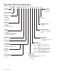
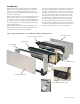
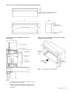
Figure 8: 16" x 42" wall sleeve with continuous flange and drip edge
16"
42"
D**
Louver Mounting Holes
Flange Height
(Standard = 1-1/4")
Flange location (from outdoor side of sleeve)
is factory provided in increments of 1/8"
X*
Drip Edge
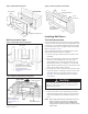
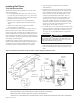
Figure 9: Wall sleeve installation for thin wall
construction
B**
Leveling Leg
to Support
Cabinet
Hydronic Heat
Coil Section
3-1/2" Thick
Batt Insulation
1-5/8" Metal Stud 16" O.C.
Window Stool
Insulation Wet Panel
X*
D**
Notes:
** See"PDANChassis&CabinetDimensions"onpage
6,fordimensions“D”and“B”.
* Dimension“X”iselddeterminedorspecied.Angle
isfactoryweldedatgivendimensionwhenoptionis
designated.
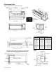
Figure 10: 16" x 42" wall sleeve with optional leveling
legs and continuous flange
16"
1-1/4"
42"
Outdoor Side of
Sleeve
X*
6-3/8"
Optional
Leveling Leg
13-3/4"
Optional
Continuous
Flange
Note: Givendimensionsarestandard.