
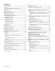
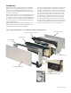
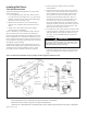
Specifications

IM 938-4 / Page 6 of 42
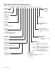
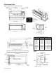
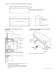
Dimensional Data
Figure 2: PDAN Chassis & Cabinet Dimensions
Note: Electrical rough-in should be located behind
kickplate (removable front) and below wall sleeve.
52" (1320mm)
1
1
⁄2"
(38mm)
19
1
⁄2"
(495mm)
Wall Space For Piping
Rough-in (Typ. R.H. & L.H.)
3"
(76mm) Min.
3"
(76mm)
Kickplate
(Removable Front)
7/8"
(22mm)
Wall Thickness
“B”
“A”
1
1
⁄
4
" (32mm)
2
7
⁄8"
(67mm)
16"
(406mm)
“D”
9
1
⁄8"
(232mm)
5
1
⁄2"
(140mm)
7/8"
(22mm)
1
5
⁄8"
(41mm)
1
5
⁄16"
(33mm)
3" (76mm) Min.
Kickplate Height
Premium,
Programmable
Digital Touchpad
Control
1
1
⁄4" Recess for Architectural Louver
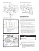
“A” – in. (mm) “D” – in. (mm) “B” – in. (mm)
Room Cabinet Wall Sleeve Wall Thickness
18
3
⁄4 (476) 13
3
⁄4 (349) 4
3
⁄4 – 5
3
⁄4 (121–146)
17
3
⁄4 (451) 13
3
⁄4 (349) 5
3
⁄4 – 6
3
⁄4 (146–171)
16
3
⁄4 (425) 13
3
⁄4 (349) 6
3
⁄4 – 7
3
⁄4 (171–197)
15
3
⁄4 (400) 13
3
⁄4 (349) 7
3
⁄4 – 8
3
⁄4 (197–222)
14
3
⁄4 (375) 13
3
⁄4 (349) 8
3
⁄4 – 9
3
⁄4 (222–248)
13
3
⁄4 (349) 13
3
⁄4 (349) 9
3
⁄4 – 10
3
⁄4 (248–273)
12
3
⁄4 (324) 13
3
⁄4 (349) 10
3
⁄4 – 11
3
⁄4 (273–298)
11
3
⁄4 (298) 13
3
⁄4 (349) 11
3
⁄4 – 12
3
⁄4 (298–324)
10
3
⁄4 (273) 13
3
⁄4 (349) 12
3
⁄4 – 13
3
⁄4 (324–349)
10
3
⁄4 (273) 14
3
⁄4 (375) 13
3
⁄4 – 14
3
⁄4 (349–375)
10
3
⁄4 (273) 15
3
⁄4 (400) 14
3
⁄4 – 15
3
⁄4 (375–400)
10
3
⁄4 (273) 16
3
⁄4 (425) 15
3
⁄4
– 16
3
⁄4 (400–425)
10
3
⁄4 (273) 17
3
⁄4 (451) 16
3
⁄4 – 17
3
⁄4 (425–451)
Standard Size Wall Sleeve