
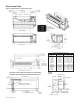
Specifications

IM 938-4 / Page 10 of 42
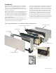
Installing Wall Sleeve
Thin Wall Construction
Applications utilizing eld supplied louvers require addi-
tional considerations:
1. Louvers supplied by others must have 70% free area or
a pressure drop not exceeding 0.05 in. w.g. (12.45 Pa) at
300 fpm (1.524 m/sec) face velocity, and a blade design
that will not cause recirculation of air.
2. Daikin does not warrant the rain and water leakage
resistance of its equipment when used with louvers by
others.
3. All louvers by others must be approved by Daikin
engineering prior to installation.
Figure 11 illustrates a typical installation using a eld sup-
plied, continuous louver. This method is for illustration
purposes only. Other variations may be employed as long as
they meet Daikin's louver specications listed above and so
long as adequate wall support is achieved. All structural sup-
ports and fasteners (except the optional top angle and turned
down ange) are eld supplied.
Installation of wall sleeves with continuous louvers is very
similar to that of applications with factory furnished louvers.
Assuming the louver meets the Daikin criteria, as stated
previously, proceed to install the wall sleeve as follows:
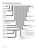
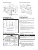
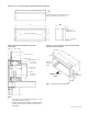
Figure 11: Wall sleeve installation using top angles and field supplied continuous louver
13
3
⁄4"
(349mm)
1
1
⁄4"
(38mm)
Insulated
Panel
Optional
Top Angle
16"
(406mm)
Outside Edge
of Sleeve
Wall Sleeve
Turndown
Flange
(See Detail)
Finished Floor
Including Carpet
Outside
Louver
By Others
Resilient
Caulking
(see Note 2)
Turndown Flange
Resilient
Caulking
(see Note 2)
Wall
Sleeve
Wall Frame
By Others
Optional
Top Angle
42"
(1069mm)
Optional
Subbase
16"
(406mm)
10
1
⁄2"
(267mm)
Max.
1"
(25mm)
3" Min.
(76mm)
Wall
Sleeve
Insulated Panel
X*
Supports
By Others
(2 Req’d.)
Min. 3
7
⁄8"
(98mm)
Notes: 1.Caulkentireperimeterofwallsleeveafterinstallation.
2.Sealareabetweenlouverandwallsleevetopreventcondenserairrecirculation.
3.Dimensionsshownintableonpage6donotapplytothisapplication.
* Dimension“X”iselddeterminedorspecied.Angleisfactoryweldedatgivendimensionwhenoptionisdesignated.
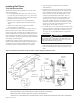
1. Clean the opening of all debris that may interfere
with installation.
2. Position the wall sleeve into the wall so that it is ush
with the exterior wall. Important: If the wall sleeve has
been installed into a thick wall, make certain the wall
sleeve protrudes into the room a minimum of 1-1/8"
(29mm) beyond the nished wall surface. This is to
accommodate the heat section and room cabinet. The
center of gravity is 10-3/4" (273mm) from the rear
face of the standard wall sleeve. If no subbase is being
employed, adequate support for the wall sleeve up to the
center of gravity must be provided at the job site. This
support can be wood, metal or concrete.
3. Level wall sleeve side to side and pitch to outside 1/8"/ft.
to assure proper sleeve drainage to outside. Anchor with
appropriate fasteners using holes provided (see Figure
14 on page 12), or drill additional holes as required to
secure rmly.
CAUTION
Do not drill holes in the base of the wall sleeve. Use
shims between the wall and the wall sleeve to prevent
wall sleeve distortion during anchoring.
4. Caulk the wall sleeve to the wall opening on both the
inside and outside perimeter. This can be done from the
inside of the building. Be careful not to plug the weep
holes.