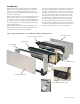
Installation & Maintenance Data IM 938-4 Group: PTAC Part Number: 910116723 Date: October 2013 Applied Packaged Terminal Air Conditioner 16" x 42" PDAN with Top-Mounted Hydronic Heat with R-410A Refrigerant Note: Installation and maintenance are to be performed only by qualified personnel who are familiar with local codes and regulations and are experienced with this type of equipment. Caution: Sharp edges and coil surfaces are potential injury hazards. ©2013 Daikin Applied • www.DaikinAP.
Contents Safety Information................................................................3 Equipment Start-up............................................................21 Inspection..............................................................................3 PTAC/PTHP Startup Report–Audit....................................22 Daikin Model PDAN Product Nomenclature.......................4 .............................................................................................22 Introduction..
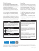
Safety Information Inspection Follow all safety codes. Wear safety glasses and work gloves. Use a quenching cloth for brazing operations. Have a fire extinguisher available. Follow all warnings and cautions in these instructions and attached to the unit. Consult applicable local building codes and National Electrical Codes (NEC) for special requirements. Recognize safety information. When you see a safety symbol on the unit or in these instructions, be alert to the potential for personal injury.
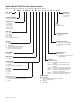
Daikin Model PDAN Product Nomenclature Note: For Illustration purposes only. Not all options available with all models.
Introduction Daikin offers the most complete line of PTAC and PTHP products for new construction projects and exact replacements for our original Singer, Remington, American Air Filter and American Standard brand equipment, and models from other manufacturers. Daikin products feature our proven institutional grade design and construction that allows you to benefit from the long life, reliability, and low sound levels, along with higher energy efficiencies for lower operating costs.
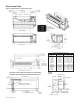
Dimensional Data Figure 2: PDAN Chassis & Cabinet Dimensions Premium, Programmable Digital Touchpad Control 11⁄4" Recess for Architectural Louver “A” – in. (mm) “D” – in. (mm) “B” – in.
CAUTION WARNING Residential and institutional cleaning compounds can cause permanent damage to the packaged terminal unit. To avoid damage to unit controls and heat transfer surfaces, do not spray cleaning compounds onto the discharge grille, return air opening, or unit controls. Normal cleaning can be accomplished by wiping the unit surface with a damp cloth.
Figure 4: Wall Sleeve Extension Figure 7: Frame and Brick Construction 24" As Required 16" x 42" Cabinet/Wall Sleeve Room Side Lintel (by others) 161/4" High 16" Air Splitters 111/8" 42" 421/4" Wide Cabinet/Wall Sleeve Rough Opening 24" 67/8" Wall Sleeve Extension Installing Wall Sleeve Thin Wall Construction Wall Construction Types Figure 5: Panel Wall (Thin) Construction Steel Studs Concrete Pillars 161/4" x 421/4" Floor Cabinet/Wall Sleeve Rough 5 5 Opening or 16 /8" x 42 /8" When using a
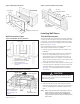
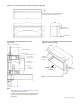
Figure 8: 16" x 42" wall sleeve with continuous flange and drip edge X* Flange location (from outdoor side of sleeve) is factory provided in increments of 1/8" D** 42" Flange Height (Standard = 1-1/4") Louver Mounting Holes 16" Drip Edge Figure 9: Wall sleeve installation for thin wall construction Figure 10: 16" x 42" wall sleeve with optional leveling legs and continuous flange B** 13-3/4" Insulation Wet Panel X* 42" Window Stool 1-5/8" Metal Stud 16" O.C.
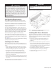
1. Clean the opening of all debris that may interfere with installation. 2. Position the wall sleeve into the wall so that it is flush with the exterior wall. Important: If the wall sleeve has been installed into a thick wall, make certain the wall sleeve protrudes into the room a minimum of 1-1/8" (29mm) beyond the finished wall surface. This is to accommodate the heat section and room cabinet. The center of gravity is 10-3/4" (273mm) from the rear face of the standard wall sleeve.
CAUTION Do not drill holes in the base of the wall sleeve. Use shims between the wall and the wall sleeve to prevent wall sleeve distortion during anchoring. B 4" Wood Stool Brick Optional Continuous Flange Outside Louver Wall Sleeve 1' to 4" A heavy-gauge, corrosion resistant wall sleeve is provided for each unit. The wall sleeve is either shipped in a separate carton or shipped in a multi-pack of 15. Typical installation for masonry walls is shown in Figure 12.
Anchoring The Wall Sleeve IMPORTANT Anchoring the wall sleeve is accomplished as shown in Figure 14. Use the rubber isolation washers with the fasteners to minimize sound transmission from the equipment to the wall, at the point of contact. A 5⁄16" (8mm) hole is provided on each side, 2" (51mm) down from the top and 2" (51mm) in from the rear of the wall sleeve. It may be necessary to drill additional holes in the wall sleeve to firmly secure it.
CAUTION Do not pull on evaporator fan housing, control box or compressor. Do not lift by pulling on the tubing. Tubing can crack or bend damaging the unit. 4. If wall sleeve has been previously installed, remove temporary weather panel. 5. Check all fasteners to make certain they have not come loose during shipment. Do not loosen bolts holding down compressor; they are set at the factory. 6. Do not lubricate motors before start-up. Motors are permanently lubricated. 7.
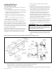
Installing Room Cabinet The room cabinet is the last piece to install. The following instructions assume all components (wall sleeve, heat section, louver and chassis) have been installed, piped and anchored. All major room construction should also be complete so as not to damage the room cabinet after it has been installed. Attaching the room cabinet can be completed as follows: 1. Firmly grasp the room cabinet and lift it over the heat section.
Controls Table 1: Keys and Indicators Labels Standard (Non-programmable) Digital Touchpad Control Figure 24: Standard Digital Touchpad Control Application 7 Push Buttons ON/OFF, FAN SPEED, MODE FAN MODE, SLEEP Temp buttons: for Temp UP and for Temp DOWN 9 LED Indicators SLEEP, COOL, COOL/DRY, FAN, HEAT, HIGH, LOW, CYCLE, CONT. LED 2 Digit Displays No Label The PTAC Digital Control is used to control a PTAC Unit that includes both an integral air conditioner and a source of heat.
Operation Memory Recall The digital control shall start with the last settings used prior to power down. These settings are saved in a non-volatile memory. Factory set mode is OFF. On/Off Triggering Control can be turned On/Off via LUI, Remote T’stat, or Sleep feature. The LUI display will show the temperature set point when the mode is Cool, Cool Dry, or Heat. The display will be blank in Fan mode. 1. On/Off triggering with LUI Control shall turn On or Off when the On/Off button is pressed in LUI.
Control Lockout Feature The control is placed in a lockout mode of operation when Mode button is held pressed for 10 seconds. Display will show “LC” to confirm Lockout Mode has been entered. Once in this Lockout Mode the control board will not take any commands at all. In Lockout, unit will continue to operate with the same settings just prior to Lockout Mode. This means the touchpad will no longer be able to pass commands to the control. User’s set point will normally be displayed.
Figure 28: If 0°F < Ts - Ts < 2°F, operation will be in Zone C On Compressor Off t 6 mins. 6 mins. On Low Fan Off t 30 secs. 30 secs. * * = Zone Determination Time Figure 29: If Ts - Tr > 5°F, operation will be in Zone D On Fan Off t Compressor On Off * 12 mins. t * = Zone Determination Time The other temperature ranges are dead bands for zone stability. Heat Mode Unit will call for heating based on the type of the heat source it has: heat pump in reverse cycle, hydronic or electric.
The Display will show the upper operating limits first. The default settings are Cool min. = 60°F and Heat max. = 85°F. 4) Fresh Air Damper Control To advance from Heat Maximum Set point, to Fresh Air Damper Control operation, press the Mode button once. Using the Up and Down buttons, toggle between "AU" for Automatic and "CL" for (forced) Closed. The Fresh Air Damper will operate when the following conditions are met: A. Damper setting in the touchpad set-up mode is “AU” (automatic) AND B.
Compressor Random Restart When power is interrupted, a random compressor restart delay of 0 to 2 minutes is initiated. In the Cool Mode only, the compressor will start operating only after the random delay plus 3 minutes (minimum off time for thermostat, ie. 2 to 5 minutes). Random delay is used only during system startup or reset. Temperature Limiting When the room temperature drops 5°F below minimum set point, the display will indicate “Lo.
Equipment Start-up Initial start-up of the Incremental® conditioners by experienced personnel is usually the responsibility of the installing contractor. This start-up consist of inspecting and operating the equipment for all functions at the time of initial installation and making necessary adjustments. It also includes demonstrating its proper operation to the owner or his agent.
PTAC/PTHP Startup Report–Audit Job Name __________________________________________ City ________________G.O. # ____________ Installer __________________________________________________________________Total No.
Premium (Programmable) Digital Touchpad Control Features LED with Program Setting Display 9-LED Indicators 8- Push Button Display Inputs Application The PTAC Digital Control is used to control a PTAC Unit that includes both an integral air conditioner and a source of heat. The Digital Control is operated with a Touchpad.
AUTO Non-Programmable Mode: • Display shows both HEAT and COOL icons • Temperature set point displays between the HEAT and COOL icons • Setpoint is adjusted with Up and Down arrows • Heating initiates when the room temperature falls one degree below the thermostat setpoint. Heating terminates when the room temperature reaches two degrees above the setpoint • Cooling initiates when the room temperature reaches one degree above the thermostat setpoint.
2.4 2.5 • • • • 2.6 To adjust the upper operating temperature limit (heat maximum set point) press and hold the Fan Speed button, and repeatedly press or buttons. The max and factory default setting is 85°F (30°C). When Control selection jumper on control board is set for “T’STAT,” the max setting can go up to 90°F (32°C).
Remote Wall Mounted Thermostats Non-Programmable Thermostat Specs Remote Thermostat Control The remote thermostat can be any thermostat that can interface with an electronic thermostat via RCBWYG terminals. The Control Selection jumper must be in T’STAT position. During a call the remote thermostat will pass R back to the controller on a respective terminal. The push buttons on the touchpad become inactive in the remote thermostat mode.
Wall-Mounted, 7, 5-2 & 5-1-1 ProgrammableThermostat Specs Standard Auto or Manual-Changeover Two-Stage Heat/ Two-Stage Cool Specs Manual Changeover One-Stage Heat and Cool or One-Stage Heat Pump Daikin Part No. 910116774 (1-Pk, White with Wall Plate) Daikin Part No.
The T9000 Wireless Temperature Control is designed to provide precision temperature control without the installation labor and expense of wiring. • Powered by AA batteries • Mounts in any suitable location that will provide good temperature control. • Large LCD display provides the user with current room temperature, set point temperature, time, program interval, and other system status information. The remote consists of 10 push-buttons • Power: Functions the same as the ON/OFF button on the touchpad.
Considerations The Remote Thermostat can be any thermostat that can interface with an electronic thermostat via RCWYBG terminals. The Control Selection jumper must be in T’STAT position. During a call the remote thermostat will pass R back to the controller on a respective terminal. The push buttons on the touchpad become inactive in the remote thermostat mode, EXCEPT in T'STAT mode, the fan speed can be changed at the Touchpad and the fan mode is dictated by the Remote t'stat.
Premium (Programmable) Digital Control Board – Jumper Placement 1– Jumper Placement to Select System Module (See Jumper Detail) A– Place jumper across AC/HYD to select Air Conditioner/Hydronic Heat. B– Place jumper across AC/E to select Air Conditioner/Electric Heat. C– Place jumper across AC/HYD/E to select Air Conditioner/Hydronic/Electric. D– Place jumper across HP to select Heat Pump E– Place jumper across HP/E to select Heat Pump/Electric.
Standard (Non-Programmable) Digital Control Board – Jumper Placement 1– Jumper Placement to Select System Module (See Jumper Detail) A– Place jumper across AC/E to select Air Conditioner with Electric Heat. B– Place jumper across HP to select Heat Pump C– Place jumper across HP/E to select Heat Pump with Electric Back-up Heat. 2– Jumper Placement to Select Fan Control A– When in Fan Cycle Mode, fan operates for 2 minutes.
Digital Control Board with Standby Power – Wiring Diagram The standby power connections, L1 STBY and L2 STBY are meant to run the indoor motor at a separate voltage from the other motors, compressor and outdoor motor. When used as such, the jumpers, JH1 and JH2, must be cut. This renders L1 & L2 and L1 STBY and L2 STBY isolated from each other. If there is no need to run the motors at a separate voltage the L1 = L1 STBY and L2 = L2 STBY. Therefore one voltage is used to run all motors.
Digital Control Board without Standby Power – Wiring Diagram The standby power connections, L1 STBY and L2 STBY are meant to run the indoormotor at a separate voltage from the other motors, compressor and outdoor motor. When used as such, the jumpers, JH1 and JH2, must be cut. This renders L1 & L2 and L1 STBY and L2 STBY isolated from each other. If there is no need to run the motors at a separate voltage the L1 = L1 STBY and L2 = L2 STBY. Therefore one voltage is used to run all motors.
Maintenance (Scheduled) Incremental conditioners are built to last. With proper care, the unit should provide uninterrupted service for many years. Scheduled maintenance of this equipment as described below, is the key to the equipment’s longevity. A. Air filters must be cleaned at regular intervals. Twice annually may be adequate in some areas while twice monthly may be required in others.
An inherent advantage of the Incremental system is that failure of any part affects only one incremental conditioner and does not interrupt the operation of the rest of the system. A further advantage is that a failed part can be quickly and easily replaced, thus minimizing the inoperative time of the equipment. This is so, however, only if a replacement part is quickly available.
Fault and Protection Codes for Applied PTAC/PTHP Control Board Fault code CE Description Cause for the fault Communication Error 1. Cable not plugged in properly on either LUI or relay board. 2. Defective cable. Sh Missing Shunt E1 Problem with IAS The user configurable shunt for System Select, Control Select Off Fan Cycle, and/or Hydronic Valve is missing or not placed properly. Indoor Air Sensor missing or short. E2 Problem with ICS Indoor Coil Sensor missing or short.
Solid State Digital Controls – Local User Interface Display Codes Fault code Description Cause for the fault AU Auto Damper Control setup indicator damper is in "automatic" mode. Au Auto HP/E Control setup indicator heat pump electric is in automatic changeover mode (HP/E). Brown Out or bo Low Voltage bY HP/E Bypass Brown Out - Control monitors input voltage to prevent relay chattering. When voltage drops below 17 VAC, outputs are disabled until voltage input increases to 20 VAC or greater.
Troubleshooting These items should be checked by a qualified service technician only. Trouble Cause 1. 2. Blowers won’t operate on cool Blowers operate on cool but compressor does not start Cure a. No power a. b. c. Faulty touchpad/thermostat. Loose connections at push-button switch. b. c Check supply line fusses, circuit breakers, and be sure the power is on.
Trouble 9. Too much cooling. Cause Cure a. b. Thermostat set too low. Defective thermostat a. b. Adjust. Replace. a. Condensate drain from evaporator to condenser plugged. Insulating seals on equipment damaged. Evaporator blower motor not up to speed. Evaporator blower incorrectly positioned. a. Remove obstructions to water flow. b. c. d. b. c. d. Adjust or replace. Check for correct voltage. Replace motor if necessary. Tighten. 11. Blowers won’t operate on Heat. a. b. c. d. e. f. No power.
Daikin Training and Development Now that you have made an investment in modern, efficient Daikin equipment, its care should be a high priority. For training information on all Daikin HVAC products, please visit us at www.DaikinAP.com and click on training, or call 540-248-9646 and ask for the Training Department. Warranty All Daikin equipment is sold pursuant to its standard terms and conditions of sale, including Limited Product Warranty. Consult your local Daikin Representative for warranty details.