
Installation manual


4 English
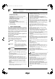
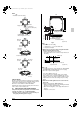
Refrigerant piping direction
To the rear (Straight piping)
To the right (Elbow required)
Upward running refrigerant piping are possible in all patterns.
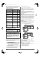
3-3 Use suspension bolts for installation. Check
whether the ceiling is strong enough to support
the weight of the unit or not. If there is a risk,
reinforce the ceiling before installing the unit.
(Installation pitch is marked on the paper pattern for installa-
tion. Refer to it to check for points requiring reinforcing.)
4. PREPARATIONS BEFORE
INSTALLATION
4-1 FOR 4-WAY AIR DISCHARGE
1. Relation of holes for indoor unit, suspension bolt posi-
tion, piping and wiring. (Refer to Fig. 2)
(Illustrations seen from ceiling)
∗ Dimensions in ( ) for 100 and 125 models
∗∗∗ Suspension bolt pitch
2. Make holes for suspension bolts, refrigerant and drain
piping, and wiring. (Refer to Fig. 3)
• Refer to the paper patten for the locations.
• Select the location for each of holes and open the holes in
the ceiling.
Fig. 3
NOTE
• All the above parts are field supplied.
(Use either a M8-M10 size bolt)
Use a hole-in anchor for existing ceilings, and a sunken insert,
sunken anchor or other field supplied parts for new ceilings to
reinforce the ceiling to bear the weight of the unit. Adjust clear-
ance from the false ceiling before proceeding further.
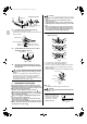
3. Detach the air intake grille and corner covers from the
indoor unit.
• Detach the air intake grille. (Refer to Fig. 4 and 5)
• Slide the locking knobs (×2) on the air intake grille inward
(direction of arrows) and lift upwards.
• Open the air intake grille to a 45
°
angle and detach from
the unit.
• Detach the corner covers.
Fig. 4
Fig. 5
[TO CHANGE AIR FLOW RATE]
• When shipped from the factory, the shutters on air outlets C
and D are closed so that air flow rate is the same in all four
directions.
• Air flow rate can be changed by sliding the shutter.
(Refer to Fig. 6 and 7)
CAUTION
Be careful not to touch the heat exchanger fins.
Air flow
direction
Fig. 1
4-way air
discharge
A
BB
C
C
D
C
C
A
D
A
C
DD
3-way air
discharge
3-way air
discharge
2-way air
discharge
2-way air
discharge
Optional parts required
(Back-to-back blocking pad kit)
790∗∗∗
895
790∗∗∗
895
30180
83
33
163
Upward running drain
piping shown above
A
B
C
D
∗ 80 (147)
∗ 58 (125)
∗ 40 (107)
Drain hose connection (VP20)
Gas piping
Liquid piping
Fig. 2
(length: mm)
50-100
Ceiling slab
Anchor
False ceiling
Suspension bolt
Long nut or turnbuckle
(length: mm)
Air intake
grille
Cornercover (×4)
Hold the indoor unit by the
hanger brackets when carrying.
Shutter
Fig. 6
01_EN_3P086156-10X.fm Page 4 Wednesday, April 15, 2009 3:48 PM