00_CV_3P086156-10X.fm Page 1 Monday, April 13, 2009 4:46 PM INSTALLATION MANUAL English SYSTEM Inverter Air Conditioners Deutsch MODELS (Ceiling suspended Cassette type) FXUQ71MV1 FXUQ100MV1 FXUQ125MV1 FXUQ71MAV1 FXUQ100MAV1 FXUQ125MAV1 Français Español Italiano ΕλληνικÜ READ THESE INSTRUCTIONS CAREFULLY BEFORE INSTALLATION. KEEP THIS MANUAL IN A HANDY PLACE FOR FUTURE REFERENCE. LESEN SIE DIESE ANWEISUNGEN VOR DER INSTALLATION SORGFÄLTIG DURCH.
EN60335-2-40, FXZQ20MVE, FXZQ25MVE, FXZQ32MVE, FXZQ40MVE, FXZQ50MVE FXCQ20MVE, FXCQ25MVE, FXCQ32MVE, FXCQ40MVE, FXCQ50MVE, FXCQ63MVE, FXCQ80MVE, FXCQ125MVE FXMQ40MVE, FXMQ50MVE, FXMQ63MVE, FXMQ80MVE, FXMQ100MVE, FXMQ125MVE, FXMQ200MVE, FXMQ250MVE FXLQ20MVE, FXLQ25MVE, FXLQ32MVE, FXLQ40MVE, FXLQ50MVE, FXLQ63MVE FXNQ20MVE, FXNQ25MVE, FXNQ32MVE, FXNQ40MVE, FXNQ50MVE, FXNQ63MVE FXHQ32MVE, FXHQ63MVE, FXHQ100MVE FXSQ20MVE, FXSQ25MVE, FXSQ32MVE, FXSQ40MVE, FXSQ50MVE, FXSQ63MVE, FXSQ80MVE, FXSQ100MVE, FXSQ125MVE
01_EN_3P086156-10X.fm Page 1 Wednesday, April 15, 2009 3:48 PM FXUQ71MV1 FXUQ100MV1 FXUQ125MV1 FXUQ71MAV1 FXUQ100MAV1 FXUQ125MAV1 VRV SYSTEM Inverter Air Conditioners CONTENTS 1. SAFETY PRECAUTIONS............................................... 1 2. BEFORE INSTALLATION .............................................. 2 3. SELECTING INSTALLATION SITE AND AIR FLOW DIRECTION ..................................................................... 3 4. PREPARATIONS BEFORE INSTALLATION ................. 4 5.
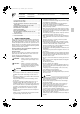
01_EN_3P086156-10X.fm Page 2 Wednesday, April 15, 2009 3:48 PM • Do not install the air conditioner in the following locations: 1. Where there is a high concentration of mineral oil spray or vapour (e.g. a kitchen). Plastic parts will deteriorate, parts may fall off and water leakage could result. 2. Where corrosive gas, such as sulphurous acid gas, is produced. Corroding of copper pipes or soldered parts may result in refrigerant leakage. 3. Near machinery emitting electromagnetic radiation.
01_EN_3P086156-10X.fm Page 3 Wednesday, April 15, 2009 3:48 PM [PRECAUTION] If installing the wireless kit in a room with electronic fluorescent lighting (inverter or rapid start type), the remote controller’s transmission distance may be shortened. Indoor units should be installed as far away from fluorescent lighting as possible.
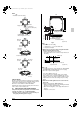
01_EN_3P086156-10X.fm Page 4 Wednesday, April 15, 2009 3:48 PM Air flow direction C D B D B Ceiling slab D C C A 4-way air discharge 3-way air 3-way air discharge discharge Optional parts required (Back-to-back blocking pad kit) C C False ceiling Long nut or turnbuckle Suspension bolt Fig. 3 (length: mm) NOTE • All the above parts are field supplied. D A 2-way air discharge 2-way air discharge Fig.
01_EN_3P086156-10X.fm Page 5 Wednesday, April 15, 2009 3:48 PM NOTE • IIlustration seen from ceiling 895 790∗∗∗ C B 180 Air discharge Shutter (Indicates drain pan.) C D B Ceiling slab Moderate flow rate B D False ceiling Long nut or turnbuckle (length: mm) NOTE • To change air flow rate, select a pattern from “TO CHANGE AIR FLOW RATE” and determine the location of piping. • All the above parts are field supplied. C B D Moderate flow rate Fig.
01_EN_3P086156-10X.fm Page 6 Wednesday, April 15, 2009 3:48 PM 4. After installing the blocking pads, attach the center retainer for blocking pad and the top decorative plate. (Refer to Fig. 13) Air intake grille Cornercover (×4) Fig. 10 Hold the indoor unit by the hanger brackets when carrying. Center retainer for blocking pad (15) (accessory) Screw for top decorative plate Insert here. Top decorative plate Insert here.
01_EN_3P086156-10X.fm Page 7 Wednesday, April 15, 2009 3:48 PM Moderate flow rate C C B Moderate flow rate D A A Blocking pad D B C Moderate flow rate Moderate flow rate C B B A Blocking pad A D D C C B Moderate flow rate B D D A Blocking pad B A Blocking pad A C D 5. A B Shutter C English Blocking pad D Shutter INDOOR UNIT INSTALLATION <
01_EN_3P086156-10X.fm Page 8 Wednesday, April 15, 2009 3:48 PM Securing the washer Piping area A B D 5-2 C Fig. 17 Insert below washer. Washer fixing plate (5) (accessory) Install the indoor unit. (Refer to Fig. 18) • Lock the unit to the hangers on side A. • Hook the unit onto the other 2 hangers and lock with bottom washers and nuts. CAUTION • Use a pipe cutter and flare suitable for the type of refrigerant. • Apply ester oil or ether oil around the flare section before connecting.
01_EN_3P086156-10X.fm Page 9 Wednesday, April 15, 2009 3:48 PM Table 2 φ9.5(3/8”) 32.7-39.9 N • m 12.8 – 13.2 φ15.9(5/8”) 61.8-75.4 N • m 19.3 – 19.7 Flare 45˚±2˚ Flare dimensions A (mm) R0.4-0.8 A Tightening torque 90˚±2˚ Pipe size • Refer to “Table 2” to determine the proper tightening torque. Not recommendable but in case of emergency You must use a torque wrench but if you are obliged to install the unit without a torque wrench, you may follow the installation method mentioned below.
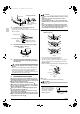
01_EN_3P086156-10X.fm Page 10 Wednesday, April 15, 2009 3:48 PM VP20 Drain hose (1) (For VP20 connection) (accessory) Ceiling slab 1 - 1.5 m Hanger bracket Elbow (10) VP20 Large sealing pad (8) (accessory) Clamp (2) (accessory) Notes on upward running drain hose Fig. 26 Rearward running piping Min. 1/100 gradient GOOD Rightward running drain hose • • • • • • WRONG Fig. 27 To keep the drain hose from sagging, space hanging wiring every 1 to 1.5m. (Refer to Fig.
01_EN_3P086156-10X.fm Page 11 Wednesday, April 15, 2009 3:48 PM WHEN ELECTRIC WIRING WORK IS FINISHED • Check drainage flow during Cooling operation, explained under “11. TEST OPERATION”. WHEN ELECTRIC WIRING WORK IS NOT FINISHED CAUTION • Electrical wiring work should be done by a certified electrician. • If someone who does not have the proper qualifications performs the work, perform the following after the test run is complete.
01_EN_3P086156-10X.fm Page 12 Wednesday, April 15, 2009 3:48 PM • • • • CAUTION When clamping wiring, use the included clamping material to prevent outside pressure being exerted on the wiring connections and clamp firmly. When doing the wiring, make sure the wiring is neat and does not cause the control box lid to stick up, then close the cover firmly. When attaching the control box lid, make sure you do not pinch any wires.
01_EN_3P086156-10X.fm Page 13 Wednesday, April 15, 2009 3:48 PM • If using group control and two remote controllers at the same time, connect remote controller 2 (SUB) to the indoor unit which is at the end of the crossover wiring (P1, P2). (See the figure below.) • Group control is not possible between ceiling suspended cassette type units and normal VRV indoor units. 3.
01_EN_3P086156-10X.fm Page 14 Wednesday, April 15, 2009 3:48 PM 10. FIELD SETTINGS 10-5 Setting air filter sign 10-1 Make sure the control box lids are closed on the indoor and BEV and outdoor units. Field setting must be made from the remote controller in accordance with the installation condition. • Setting can be made by changing the “Mode No.”, “FIRST CODE NO.”, and “SECOND CODE NO.”. • The “Field Settings” included with the remote control lists the order of the settings and method of operation.
00_CV_3P086156-10X.