INSTALLATION MANUAL SYSTEM Inverter Air Conditioners MODELS Air Handling Unit FXTQ12PAVJU FXTQ18PAVJU FXTQ24PAVJU FXTQ30PAVJU FXTQ36PAVJU FXTQ42PAVJU FXTQ48PAVJU FXTQ54PAVJU English Français Español Read these instructions carefully before installation. Keep this manual in a handy place for future reference. This manual should be left with the equipment owner. Lire soigneusement ces instructions avant l’installation. Conserver ce manuel à portée de main pour référence ultérieure.
VRV SYSTEM Inverter Air Conditioners CONTENTS 1. 2. 3. 4. 5. 6. 7. 8. 9. 10. 1. SAFETY CONSIDERATIONS ........................................... 1 BEFORE INSTALLATION .................................................. 3 SELECTING INSTALLATION SITE ................................... 3 PREPARATIONS BEFORE INSTALLATION AND INSTALLATION.................................................................. 4 REFRIGERANT PIPING WORK ....................................... 6 DRAIN PIPING WORK ....................
• It is recommended to install a ground fault circuit interrupter if one is not already available. This helps prevent electrical shocks or fire. • The indoor unit is for R-410A. See the catalog for indoor models that can be connected. Normal operation is not possible when connected to other units. • Securely fasten the outside unit terminal cover (panel). If the terminal cover/panel is not installed properly, dust or water may enter the outside unit causing fire or electric shock.
2. FOR THE FOLLOWING ITEMS, TAKE SPECIAL CARE DURING CONSTRUCTION AND CHECK AFTER INSTALLATION IS FINISHED. BEFORE INSTALLATION WARNING • Entrust installation to the place of purchase or a qualified serviceman. Improper installation could lead to leaks and, in worse cases, electric shock or fire. • Use of unspecified parts could lead to the unit falling, leaks and, in worse cases, electric shock or fire. NOTE • Be sure to read this manual before installing the indoor unit.
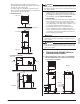
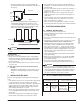
• Where piping between indoor and outdoor units is possible within the allowable limit. (Refer to the installation manual for the outdoor unit.) • If a return-air duct is not installed, carefully select the place and method of product installation so that air flow into the product will not be blocked. WARNING • When installing the unit horizontally, be sure to tilt the unit in the direction shown in Fig. 1-2. If the unit is tilted in any other way, water can leak.
Table 1 Model 12 · 18 type 24 · 30 · 36 · 42 · 48 · 54 type (4) Check if the unit is horizontally level. A 463/4 531/4 B 22 24 C 171/2 20 D 191/2 22 E 10 12 F G H I 14- 11- 17- 171/2 15/16 1/8 15/16 14- 11- 19- 191/2 15/16 5/8 15/16 (2) Make sure the range of the unit’s external static pressure is not exceeded. (up to 0.5 in.W.C. at “H” speed.) CAUTION • Make sure the unit is installed level using a level tube: four sides.
5. REFRIGERANT PIPING WORK 〈Observe the requirements listed below for refrigerant piping sizes.〉 Liquid Gas 12 · 18 type 1/4 in. 1/2 in. 24 · 30 · 36 · 42 · 48 · 54 type 3/8 in. 5/8 in. 〈Execute heat insulation work completely on both sides of the gas piping and the liquid piping or else a water leakage might result. Failing to insulate the pipes may cause leaking or burns.
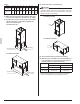
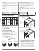
(1) Install drain piping as described Fig. 6. CAUTION • Be sure to insulate any field piping all the way to the piping connection inside the unit. Any exposed piping may cause condensation or burns if touched. In case of vertical installation • When brazing the refrigerant piping, perform nitrogen replacement first, or perform the brazing while feeding nitrogen into the refrigerant piping. (Refer to Fig.
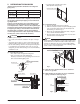
• To keep the piping from becoming clogged with dirt, avoid bends where possible and install so that traps can be cleaned. Air handler At least 4 in. At least 3 in. Fig. 7 • Observe the following guidelines when installing concentrated drain piping. Select the thickness of the concentrated drain piping to reflect the capacity of the machine to which it will be connected. (Install a drain trap for each indoor unit.) (Refer to Fig.
NOTES 1. If the wiring is in a place where people it can be easily touched by people, install a ground-fault circuit interrupter to prevent electric shock. 2. When using a ground-fault circuit interrupter, make sure to select one useful also to protection against overcurrent and short-circuit. When using a ground-fault circuit interrupter only for grounding device, make sure to use a wiring interrupter together. • The length of the transmission wiring and remote controller wiring are as follows.
in Fig. 10. • Then secure them in place with the included clamp material (1) as shown in Fig. 10 to protect them from external force from outside the unit. • If the power supply voltage is 208V, change the transformer wire connection from the 240V terminal to the 208V terminal. (Refer to Fig. 11) How to use insulation tube. • Use the insulation tube to cover the wiring. • Joint the insulation tube with the tape and cut off the tube sticking out of the unit.
• Outside the air conditioners, separate the low voltage wiring (remote controller and transmission wiring) and high voltage wiring (ground wire and power supply wiring) by at least 5 in. so that they do not pass through the same place together. Proximity may cause electrical interference, malfunctions, and breakage. [ PRECAUTIONS ] • Refer to the “REMOTE CONTROLLER INSTALLATION MANUAL” on how to install and lay the wiring for the remote controller.
Wiring Method (See ‘‘8. ELECTRIC WIRING WORK’’) 10. FIELD SETTING AND TEST RUN (3) Remove the electric component box cover. 〈Field settings may have to be performed using the remote controller, depending on the type of installation.〉 (4) Add remote controller 2 (SUB) to the terminal block for remote controller (P¹, P²) in the electric component box. (There is no polarity.
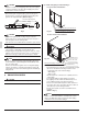
(2) Insert the air filter as far as it can go. 10-2 REMOTE CONTROL SETTING • Forced off and ON/OFF operation should be selected by selecting the SECOND CODE NO. as shown in Table 4. Table 4 External ON/OFF input Mode No. Forced off ON/OFF operation 12 (22) FIRST SECOND CODE NO. CODE NO. 01* 1 02 * factory set • Input A of forced off and ON/OFF operation work as shown in Table 5.
(1) Turn off power supply to all indoor and outdoor units. (2) Remove the front panel (upper) and the electric heater slot cover. (5) Install the circuit breaker mounting bracket removed in step (3) into the blower deck. * The HKR-03 and HKR-06 have no circuit breaker mounting bracket; Procure and install a circuit breaker. Electric heater slot cover (6) Connect the relay connector of the heater kit to the relay connector of the product.
(8) Pass the power supply wiring and the ground wire through the conduit (conduit should be field supplied). The hole for running wires through should be sealed completely to prevent air from entering. (11) Confirm that there are no mistakes with the wiring, and install the front panel (upper). Pass through the conduit Power supply wiring and ground wire (9) Select the corresponding electric heater from the electrical wiring diagram and mark the checkbox ( for the electric heater with “ ”.
(12) -2 Electric heater operating mode setting 〈When electric heater is used in “Heat Pump lockout mode”〉 • Check the heater capacity. (Select heater marked with “ ” or “ 2” in Table 8.) • Perform on-site setting using the remote controller. • Set the “heat pump lockout mode” using the outdoor unit. (Refer to the service manual for the outdoor unit.) 〈When used as “Auxiliary electric heater”〉 • Check the heater capacity. (Select heater marked with “ 1” in Table 8.
〈When using a wireless remote controller〉 • A wireless remote controller address needs to be set when using a wireless remote controller. See the installation manual included with the wireless remote controller for details on how to make the settings. Perform a test run according to the outdoor unit’s installation manual. • The operation lamp of the remote controller will flash when a malfunction occurs. Check the malfunction code on the liquid crystal display to identify the point of trouble.
3P250363-2B EM09A034A (1011) FS