
Specifications


Installation EDUS391000-F12
26 FXTQ-PA
3P250363-2B
13 English
REMOTE CONTROL SETTING10-2
Forced off and ON/OFF operation should be selected by •
selecting the SECOND CODE NO. as shown in Table 4.
Table 4
External ON/OFF input Mode No.
FIRST
CODE NO.
SECOND
CODE NO.
Forced off
12 (22) 1
01*
ON/OFF operation 02
* factory set
Input A of forced off and ON/OFF operation work as shown •
in Table 5.
Table 5
Forced off ON/OFF operation
Input A “on” to force a stop
(remote controller reception
prohibited)
Unit operated by changing input
A from “off” to “on”
Input A “off” to allow remote
controller
Unit stopped by changing input A
from “on” to “off”
SETTING THE FILTER SIGN DISPLAY INTERVAL10-3
Explain the following to the customer if the fi lter dirt settings •
have been changed.
The fi lter sign display time is set to 2500 hours (equivalent •
to 1 year’s use) when shipped.
The settings can be changed to not display.•
When installing the unit in a dusty place, set the fi lter sign •
display time to shorter intervals (1,250 hours).
Explain it to the customer that the fi lter needs to be cleaned •
regularly to prevent clogging and also the time that is set.
Mode No. FIRST CODE NO.
SECOND
CODE NO.
01 02
10 (20)
0 Filter dirt low high
1 (low/high)
Displayed time
(units: hours)
2500/
1250
10000/
5000
3 Filter sign display ON OFF
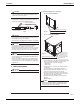
INSTALLATION OF THE OPTIONAL AIR FILTER10-4
Purchase and install the air fi lter as in Table 6.•
Table 6
Air fi lter
12 · 18 type FIL 36-42
24 · 30 · 36 · 42 · 48 · 54 type FIL 48-61
Take off the part on the bottom of the front panel.(1)
Insert the air fi lter as far as it can go.(2)
Air filter (optional accessories)
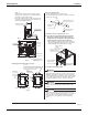
INSTALLATION OF THE ELECTRIC HEATER KIT10-5
WARNING
All phases of the electrical installation must comply with
national, state, provincial, and local codes.
When connecting an electric heater, be sure to install a
GROUNDleakaGEBREAKER
)FAGROUNDCIRCUITISNOTINSTALLEDELECTRICAL
shock or fi re may result.
Regarding the rated current of the GROUND leakage circuit
breaker to be installed, refer to the H.M.C.A. value indicated
on the manufacturer’s label or in a technical document.
The recommended rapid sensitive current and tripping time
are indicated below.
Recommended specifi cations of circuit breaker
Rapid sensitive current 30mA
Tripping time 0.1sec
Purchase and install the electric heater kit as in Table 7.•
Also refer to the installation and operating instructions that •
come with the electric heater kit.
The indoor unit fan operates at H speed during HEATER •
operation.
Table 7
Model
Electric heater kit model name
HKR-
03
HKR-
05C
HKR-
06
HKR-
08C
HKR-
10C
HKR-
15C
HKR-
20C
12 type
18 type
1
24 type
1
30 · 36 type
1 1
42 type
1 1 1 1 2
48 · 54 type
1 1 1 1 2 2
1
: Auxiliary and Heat Pump Lockout: Electric heater opera-
tion with heat pump is allowed.
: Heat Pump Lockout: Only electric heater operation is
allowed. Heat pump and electric heater cannot operate at
the same time.
2
:
Heat Pump Lockout: Only electric heater operation is al-
lowed. Heat pump and electric heater cannot operate at the
same time. In addition, acceptable 2 step heating control.