
Specifications


EDUS391000-F12 Installation
FXTQ-PA 25
3P250363-2B
English 12
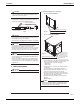
Wiring Method (See ‘‘8. ELECTRIC WIRING WORK’’)
Remove the electric component box cover.(3)
Add remote controller 2 (SUB) to the terminal block (4)
for remote controller (P
¹
, P
²
) in the electric component
box.
(There is no polarity.)
Remote controller wiring
terminal block
Remote
controller 2
(SUB)
Remote
controller 1
(MAIN)
1
P
2
P
1
F
2
F
1
T
2
T
FORCED
OFF
REMOTE
CONTRL
TRANSMISSION
WIRING
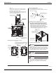
[ PRECAUTIONS ]
Crossover wiring is needed when using group control and 2 •
remote controllers at the same time.
Connect the indoor unit at the end of the crossover wire (P•
¹
,
P
²
) to remote controller 2 (SUB).
Indoor unit 1 Indoor unit 2
Max. No. of
indoor units
Crossover wire (P
1
.
P
2)
Remote controller 1
(MAIN)
Remote controller 2
(SUB)
REMOTE CONTROL (FORCED OFF AND ON/9-3
OFF OPERATION)
Connect input lines from the outside to the terminals T•
¹
and
T
²
on the terminal block (6P) for remote controller to achieve
remote control.
See the “• 10. FIELD SETTING AND TEST RUN” for details
on operation.
Input A
1
P
2
P
1
F
2
F
1
T
2
T
FORCED
OFF
REMOTE
CONTRL
TRANSMISSION
WIRING
Wire specifi cation Sheathed vinyl cord or cable (2 wires)
Gauge AWG18 – 16
Length Max. 328 ft.
External terminal
Contact that can ensure the minimum
applicable load of 16 V DC, 1 mA.
CENTRALIZED CONTROL9-4
For centralized control, it is necessary to designate the •
group No. For details, refer to the manual of each optional
controller for centralized control.
FIELD SETTING AND TEST RUN10.
〈Field settings may have to be performed using the re-
mote controller, depending on the type of installation.〉
Make sure the electric component box covers are (1)
closed on the indoor and outdoor units.
Depending on the type of installation, make the fi eld (2)
settings from the remote controller after the power is
turned on, following the “Field Settings” manual which
came with the remote controller.
The settings can select “Mode No.”, “FIRST CODE NO.” •
and “SECOND CODE NO.”.
The “Field Settings” included with the remote controller •
lists the order of the settings and method of operation.
SETTING
Mode No.
FIELD SET
MODE
SECOND
CODE NO.
FIRST
CODE NO.
Lastly, make sure the customer keeps the “Field Settings” •
manual, along with the operating manual, in a safe place.
SETTINGS WHEN USING THE OPTIONAL RE-10-1
MOTE SENSOR
This product does not include an air inlet thermistor.
It uses a remote controller thermistor for control purposes.
For this reason, it is necessary to install an optional remote
thermistor in the following cases:
When the remote controller will be installed at a location •
where it cannot accurately measure the indoor temperature.
When using a remote controller without a built-in thermistor •
(simple remote controller, wireless remote controller, no
remote controller).
When using an optional remote sensor, change the settings as
described Table 3:
Table 3
Mode No.
FIRST
CODE NO.
SECOND
CODE NO.
To use both the remote
controller thermistor and the
remote sensor
10 (20) 2
01
To use only the remote sensor 02
To use only the remote
controller thermistor
03*
* factory set