
Installation manual


7 English
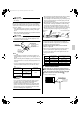
• Keep piping as short as possible and slope it downwards
so that air may not remaine trapped inside the pipe.
• Keep pipe size equal to or greater than that of the con-
necting pipe (Vinyl pipe of 1in. nominal diam. and
1-1/4in. outer diam.).
• Insulate the clamp metal with the sealing pad.
•
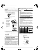
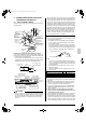
There is negative pressure inside the unit relative to atmo-
spheric pressure when the unit is running, so be sure to
provide drain frap on the drain outlet. (See the figure)
• In order to prevent foreign matter from building up
inside the piping, you should avoid curves as much
as possible.
NOTE
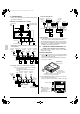
•
If converging multiple drain pipes, install according to the pro-
cedure shown below. (Install a drain trap for each indoor unit.)
• A drain trap need not be installed.
• The diameter of the piping is the same as that of the con-
necting pipe (PS1B), and should be kept equal to or
greater than that of the connecting pipe.
(2) After piping work is finished, check drainage flows
smoothly.
• Open the water supply port, add appximately 61in
3
. of water
slowly into the drain pan and check drainage flow.
CAUTION
• Drain piping connections
Do not connect the drain piping directly to sewage pipes that
smell of ammonia. The ammonia in the sewage might enter
the indoor unit through the drain pipes and corrode the heat
exchanger.
8. ELECTRIC WIRING WORK
8-1 GENERAL INSTRUCTIONS
• All field supplied parts and materials and electric works must
conform to local codes.
• Use copper wire only.
• For electric wiring work, refer to also “Wiring diagram label”
attached to the electrical components box lid.
• For remote controller wiring details, refer to the installation
manual attached to the remote controller.
• All wiring must be performed by an authorized electrician.
• This system consists of multiple indoor units. Mark each
indoor unit as unit A, unit B..., and be sure the terminal board
wiring to the outdoor unit and BS unit are properly matched.
If wiring and piping between the outdoor unit and an indoor
unit are mismatched, the system may cause a malfunction.
• A ground fault circuit interrupter capable of shutting down
power supply to the entire system must be installed.
• Refer to the installation manual attached to the outdoor unit
for the size of power supply wiring connected to the outdoor
unit, the capacity of the ground fault circuit interrupter and
switch, and wiring instructions.
• Be sure to ground the air conditioner.
• Do not connect the ground wire to gas and water pipes, light-
ning rods, or telephone ground wires.
• Gas pipes : might cause explosions or fire if gas leaks.
• Water pipes : no grounding effect if hard vinyl piping is
used.
• Telephone ground wires or lightning rods : might cause
abnormally high electric potential in the ground during
lighting storms.
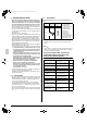
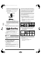
8-2 ELECTRICAL CHARACTERISTICS
MCA: Min. Circuit Amps (A); MFA: Max. Fuse Amps (A)
kW: Fan Motor Rated Output (kW); FLA: Full Load Amps (A)
8-3 SPECIFICATIONS FOR FIELD SUPPLIED
FUSES AND WIRE
NOTE
1. Allowable length of transmission wiring between indoor/out-
door units and between the indoor unit and the remote con-
troller is as follows.
(1) Outdoor unit – Indoor unit:
Max. 3280ft. (Total wiring length: 6560ft.)
(2) Indoor unit – Remote controller:
Max. 1640ft.
Metal clamp
Drain hoseTape
1/8in. or less
Drain hose
Sealing pad
(Field supply)
Metal clamp
(Field supply)
3-15/16in.
or more
Units Power supply Fan motor
Model Hz Volts
Voltage
range
MCA MFA W FLA
FXMQ72MVJU
60
208-
230
Max. 253
Min. 187
9.5 15
380×2
7.6
FXMQ96MVJU
10.7 15
380×2
8.6
Model
Power supply wiring
Remote controller wiring
Transmission wiring
Field fuses
Size Wire Size
FXMQ72MVJU
15A
Size must
comply
with local
codes.
Sheathed
wire
(2 wire)
AWG
18-16
FXMQ96MVJU
01_EN_3P086156-13Y.fm Page 7 Wednesday, September 16, 2009 2:22 PM