00_CV_3P086156-13Y.fm Page 1 Wednesday, September 9, 2009 2:52 PM INSTALLATION MANUAL SYSTEM Inverter Air Conditioners MODELS Ceiling-mounted Duct type FXMQ72MVJU FXMQ96MVJU English Français READ THESE INSTRUCTIONS CAREFULLY BEFORE INSTALLATION. KEEP THIS MANUAL IN A HANDY PLACE FOR FUTURE REFERENCE. LIRE SOIGNEUSEMENT CES INSTRUCTIONS AVANT L’INSTALLATION. CONSERVER CE MANUEL A PORTEE DE MAIN POUR REFERENCE ULTERIEURE. LEA CUIDADOSAMENTE ESTAS INSTRUCCIONES ANTES DE INSTALAR.
01_EN_3P086156-13Y.fm Page 1 Wednesday, September 16, 2009 2:22 PM VRV SYSTEM Inverter Air Conditioners CONTENTS 1. 2. 3. 4. 5. 6. 7. 8. 9. SAFETY CONSIDERATIONS ..........................................1 BEFORE INSTALLATION.................................................3 SELECTING INSTALLATION SITE ..................................4 PREPARATIONS BEFORE INSTALLATION ....................4 INDOOR UNIT INSTALLATION........................................5 REFRIGERANT PIPING WORK ........................
01_EN_3P086156-13Y.fm Page 2 Wednesday, September 16, 2009 2:22 PM • Securely fasten the outside unit terminal cover (panel). If the terminal cover/panel is not installed properly, dust or water may enter the outside unit causing fire or electric shock. • When installing or relocating the system, keep the refrigerant circuit free from substances other than the specified refrigerant (R-410A) such as air.
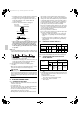
01_EN_3P086156-13Y.fm Page 3 Wednesday, September 16, 2009 2:22 PM 2. BEFORE INSTALLATION • When moving the unit while removing it from the carton box, be sure to lift it by holding on to the four lifting lugs without exerting any pressure on other parts, especially, the refrigerant piping, drain piping, and other resin parts. • Be sure to check the type of R410A refrigerant to be used before installing the unit. (Using an incorrect refrigerant will prevent normal operation of the unit.
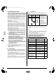
01_EN_3P086156-13Y.fm Page 4 Wednesday, September 16, 2009 2:22 PM b. Items to be checked at time of delivery Also review the “SAFETY CONSIDERATIONS” Items to be checked Check Did you explain about operations while showing the instruction manual to your customer? (2) Use suspension bolts for installation. Check whether the ceiling is strong enough to support the weight of the unit or not. If there is a risk, reinforce the ceiling before installing the unit.
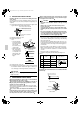
01_EN_3P086156-13Y.fm Page 5 Wednesday, September 16, 2009 2:22 PM 5. INDOOR UNIT INSTALLATION Installing optional accessories before installing the indoor unit is easier. As for the parts to be used for installation work, be sure to use the provided accessories and specified parts designated by our company. (1) Fix the hanger bracket to the suspension bolt. Tighten both upper and lower nuts firmly using washers.
01_EN_3P086156-13Y.fm Page 6 Wednesday, September 16, 2009 2:22 PM CAUTION Over-tightening may damage the flare and cause a refrigerant leakage. Use “ Table 2 ” as a reference if a torque wrench is not available. Once work is complete, make sure there is no gas leaking. As the flare nut is tightened with the wrench, the torque will suddenly increase. From that position, tighten the nut to the angle shown on “ Table 2 ”.
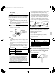
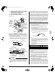
01_EN_3P086156-13Y.fm Page 7 Wednesday, September 16, 2009 2:22 PM • Keep piping as short as possible and slope it downwards so that air may not remaine trapped inside the pipe. • Keep pipe size equal to or greater than that of the connecting pipe (Vinyl pipe of 1in. nominal diam. and 1-1/4in. outer diam.). • Insulate the clamp metal with the sealing pad. Metal clamp (Field supply) Sealing pad (Field supply) Drain hose 1/8in.
01_EN_3P086156-13Y.fm Page 8 Wednesday, September 16, 2009 2:22 PM 9. WIRING EXAMPLE AND HOW TO SET THE REMOTE CONTROLLER 9-1 HOW TO CONNECT WIRINGS (Remove the electrical components box lid and wire as shown in the figure below.
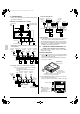
01_EN_3P086156-13Y.fm Page 9 Wednesday, September 16, 2009 2:22 PM 9-2 WIRING EXAMPLE 3. When including BS unit • Fit the power supply wiring of each unit with a switch and fuse as shown in the drawing. Power supply 208-230V 60Hz COMPLETE SYSTEM EXAMPLE (3 SYSTEMS) Control box IN/D OUT/D F1 F2 F1 F2 L1 L2 No.
01_EN_3P086156-13Y.fm Page 10 Wednesday, September 16, 2009 2:22 PM Wiring Method (See ‘‘ELECTRIC WIRING WORK’’) 10. FIELD SETTING (3) Remove the electrical components box lid Make sure the terminal box lids are closed on the indoor and outdoor units. Field setting must be made from the remote controller in accordance with the installation condition. • Setting can be made by changing the “Mode No.”, “FIRST CODE NO.”, and “SECOND CODE NO.”.
00_CV_3P086156-13Y.fm Page 2 Wednesday, September 9, 2009 2:52 PM 1645 Wallace Drive, Suite 110 Carrollton, TX 75006 info@daikinac.com www.daikinac.