
Installation manual
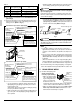
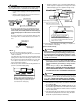
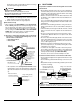
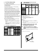
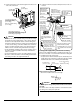
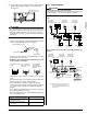
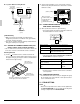
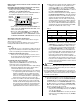
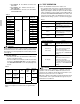
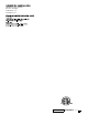
Table Of Contents
- INSTALLATION MANUAL
- 1. SAFETY CONSIDERATIONS
- 2. BEFORE INSTALLATION
- 3. SELECTING INSTALLATION SITE
- 4. PREPARATIONS BEFORE INSTALLATION
- 5. INDOOR UNIT INSTALLATION
- 6. REFRIGERANT PIPING WORK
- 7. DRAIN PIPING WORK
- 8. DUCT WORK
- 9. ELECTRIC WIRING WORK
- 10. WIRING EXAMPLE AND HOW TO SET THE REMOTE CONTROLLER
- 11. FIELD SETTING
- 12. TEST OPERATION
14 English
No. 3 system: When including BS unit
[ PRECAUTIONS ]
1. Make sure that the ground fault circuit interrupter is
designed to protect the air conditioner from ground faults,
overloads, and short-circuiting.
2. The remote controller wiring (P1 and P2) and transmission
wiring (F1 and F2) have no polarity.
10-3
CONTROL BY 2 REMOTE CONTROLLERS (Con-
trolling 1 indoor unit by 2 remote controllers)
• Set one of the remote controllers to main and the other to sub
in the case of remote control with two remote controllers.
Switching Main/Sub
(1) Insert a screwdriver into the clearance between the
grooves of the lower casing and the upper casing to remove
the upper casing. (2 grooves) (The remote controller PCB is
attached to the upper casing.)
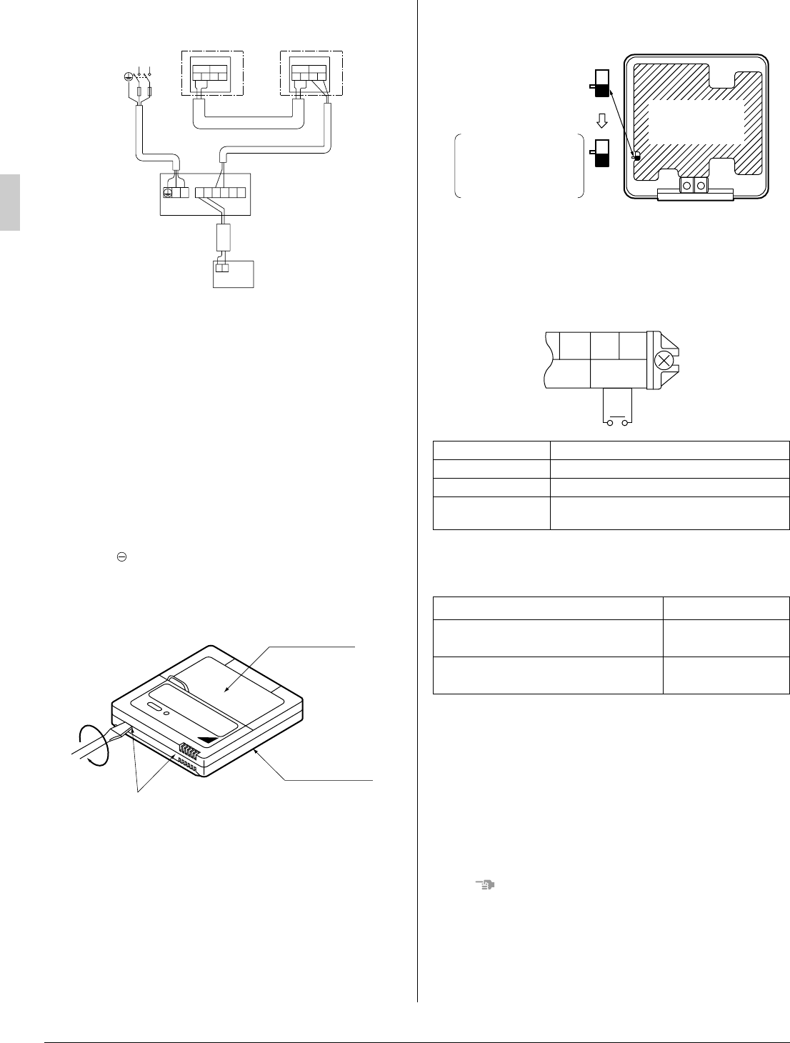
(2) Set the main/sub switch on one of the remote controller
PCBs to sub. (Keep the switch of the other remote controller
PCB set to main.)
10-4 COMPUTERISED CONTROL (FORCED OFF
AND ON/OFF OPERATION)
(1) Wire specifications and how to perform wiring
• Connect the input from outside to terminals T1 and T2 of
the terminal block for remote controller.
(2) Actuation
• The following table explains FORCED OFF and ON/OFF
OPERATIONS in response to Input A.
(3) How to select FORCED OFF and ON/OFF OPERATION
• Turn the power on and then use the remote controller to
select operation.
10-5 CENTRALIZED CONTROL
• For centralized control, it is necessary to designate the group
No. For details, refer to the manual of each optional control-
lers for centralized control.
11. FIELD SETTING
NOTE
• Before the test operation of the outdoor unit as explained in
12. TEST OPERATION, be sure to make the following field
settings as explained in 11. FIELD SETTING.
Outdoor unit
BS unit
L1 L 2
Indoor unit A
Remote controller
(option)
F
F
1
2
F
F
12
F
F
1
2
F
F
12
IN/D
IN/D
OUT/D OUT/D
1
PP
21
F
2
L
2
F
L
1
12
TT
1
P
2
P
Power supply
single phase
60Hz 208/230V
Lower part of
remote controller
Upper part of
remote controller
Insert the screwdriver here and gently work
off the upper part of remote controller.
Wire specification Sheathed vinyl cord or cable (2 wire)
Gauge AWG18-16
Length Max. 328 ft
External terminal
Contact that can ensure the minimum appli-
cable load of 15 V DC, 1 mA.
FORCED OFF ON/OFF OPERATION
Input “ON” stops operation (impossible by
remote controllers.)
Input OFF → ON turns
ON unit.
Input OFF enables control by remote con-
troller.
Input ON → OFF turns
OFF unit.
Only one remote
controller needs to be
changed if factory
settings have
remained untouched.
S
M
S
S
M
(Factory setting)
Remote controller
PC board
F2 T1 T2
FORCED
OFF
Input A