
Installation manual
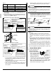
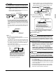
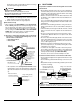
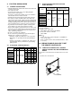
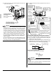
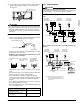
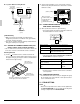
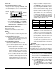
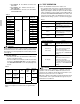
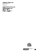
Table Of Contents
- INSTALLATION MANUAL
- 1. SAFETY CONSIDERATIONS
- 2. BEFORE INSTALLATION
- 3. SELECTING INSTALLATION SITE
- 4. PREPARATIONS BEFORE INSTALLATION
- 5. INDOOR UNIT INSTALLATION
- 6. REFRIGERANT PIPING WORK
- 7. DRAIN PIPING WORK
- 8. DUCT WORK
- 9. ELECTRIC WIRING WORK
- 10. WIRING EXAMPLE AND HOW TO SET THE REMOTE CONTROLLER
- 11. FIELD SETTING
- 12. TEST OPERATION
English 13
(4) Put the control box lid, and wrap the wire sealing material
(Small) (10) around the conduit so as to block the wire
through holes.
CAUTION
• After all the wiring connections are done, fill in any gaps in the
through holes with putty or insulation (procured locally) to pre-
vent small animals and insects from entering the unit from
outside. (If any do get in, they could cause short circuits in the
control box.)
[Precautions for Power Supply Wiring]
• Connect round crimp-style terminals provided with insulation
sleeves to the terminal block for power supply.
Be sure to follow the instructions provided below if the spec-
ified terminals cannot be used.
Otherwise, abnormal heat may be generated as a result
of the loosening of the wires.
• If stranded wires are used, do not solder the front end of the
wires.
• Connect proper wires securely and fix the wires so that exter-
nal force will not be imposed on the terminals.
• Use an appropriate screwdriver to tighten the terminal
screws. The screw heads may be damaged if the screwdriver
is too small and the terminal screws will not be tightened
properly.
• Do not tighten the terminal screws excessively, or otherwise
the screw heads may be damaged.
• Refer to the table below for the required tightening torque val-
ues of the terminal screws.
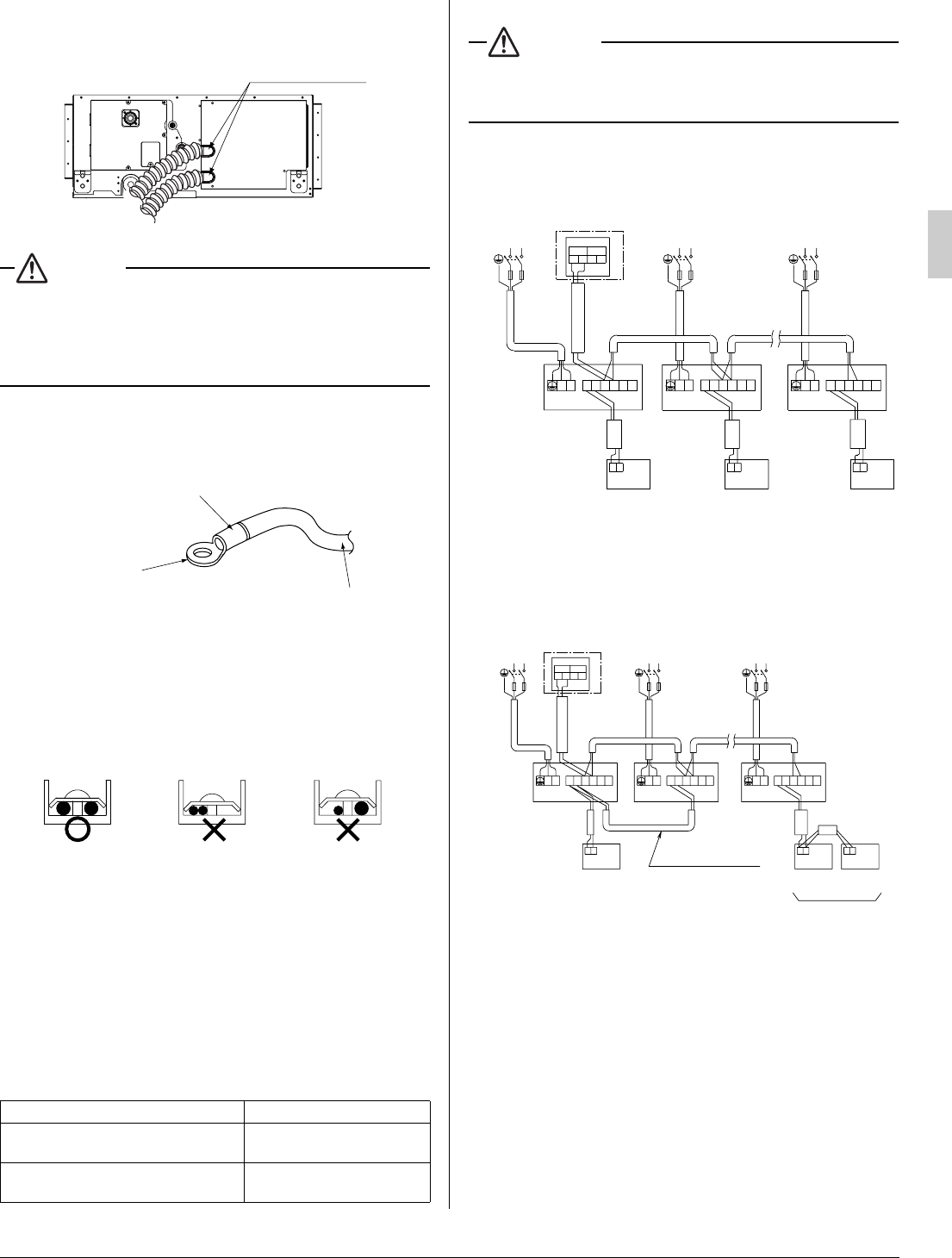
10-2 WIRING EXAMPLE
WARNING
Install a ground fault circuit interrupter.
The installation of a ground fault circuit interrupter is imperative
for the prevention of electric shocks and fire accidents.
No. 1 system: When using 1 remote controller for 1 indoor
unit
No. 2 system: For group control or use with 2 remote con-
trollers
Tightening torque (lbf·ft)
Terminal block for remote controller
and transmission wires
0.58 - 0.72
Terminal block for power supply
Ground wiring
0.87 - 1.06
Wire through holes
Electric wire
Round crimp-style terminal
Attach insulation sleeve
Connect the wires
evenly.
Do not connect a
wire to the single
side only.
Do not connect
wires different
from each other in
diameter.
Indoor unit A Indoor unit B
Most
downstream
Indoor unit
Power supply
single phase
60Hz 208/230V
Power supply
single phase
60Hz 208/230V
Power supply
single phase
60Hz 208/230V
Outdoor unit
FT
1
L
1
1
1
1
PP
2
P
L
2
1
2
P
T
F
2
F
P
F
1
2
2
2
P
1
L
2
2
P
2
F
IN/D
1
OUT/D
1
P
F
2
F
1
P
L
1
F
1 2
T
2
T
1
PP
21
F
2
L
2
F
L
1
12
TT
P
Remote controller Remote controller Remote controller
L1 L2
(option) (option) (option)
L1 L2 L1 L2
Outdoor unit
Note) There is not need to set the indoor unit
address when using group control.
(It is automatically set when the power
is turned on.)
Indoor
unit A
Indoor unit B
Most down-
stream
indoor unit
For use with 2
remote controllers
Case of group control
L1 L2 L1 L2 L1 L2
Remote controller
Remote controller
(option)
Remote controller
1
P
2
P
1
P
2
P
1
P
2
P
1
PP
21
F
2
L
2
F
L
1
L
2
L
1
12
FF
12
FF
12
TT
1
PP
21
F
2
F
12
TT
L
2
L
1
1
PP
21
F
2
F
12
TT
IN/D
OUT/D
(option)
Power supply
single phase
60Hz 208/230V
Power supply
single phase
60Hz 208/230V
Power supply
single phase
60Hz 208/230V